Controlled tension mechanism for looms

A technology of tension mechanism and loom, applied in knitting, weft knitting, warp knitting and other directions, can solve the problems of poor weaving effect and achieve good effect

Inactive Publication Date: 2013-02-27
SUZHOU HUALONG KNITTING TEXTILE
View PDF5 Cites 1 Cited by
  • Summary
  • Abstract
  • Description
  • Claims
  • Application Information

AI Technical Summary

Problems solved by technology

[0002] In the prior art, there is usually no tension cont

Method used


Image

  • Controlled tension mechanism for looms

Examples


Embodiment Construction

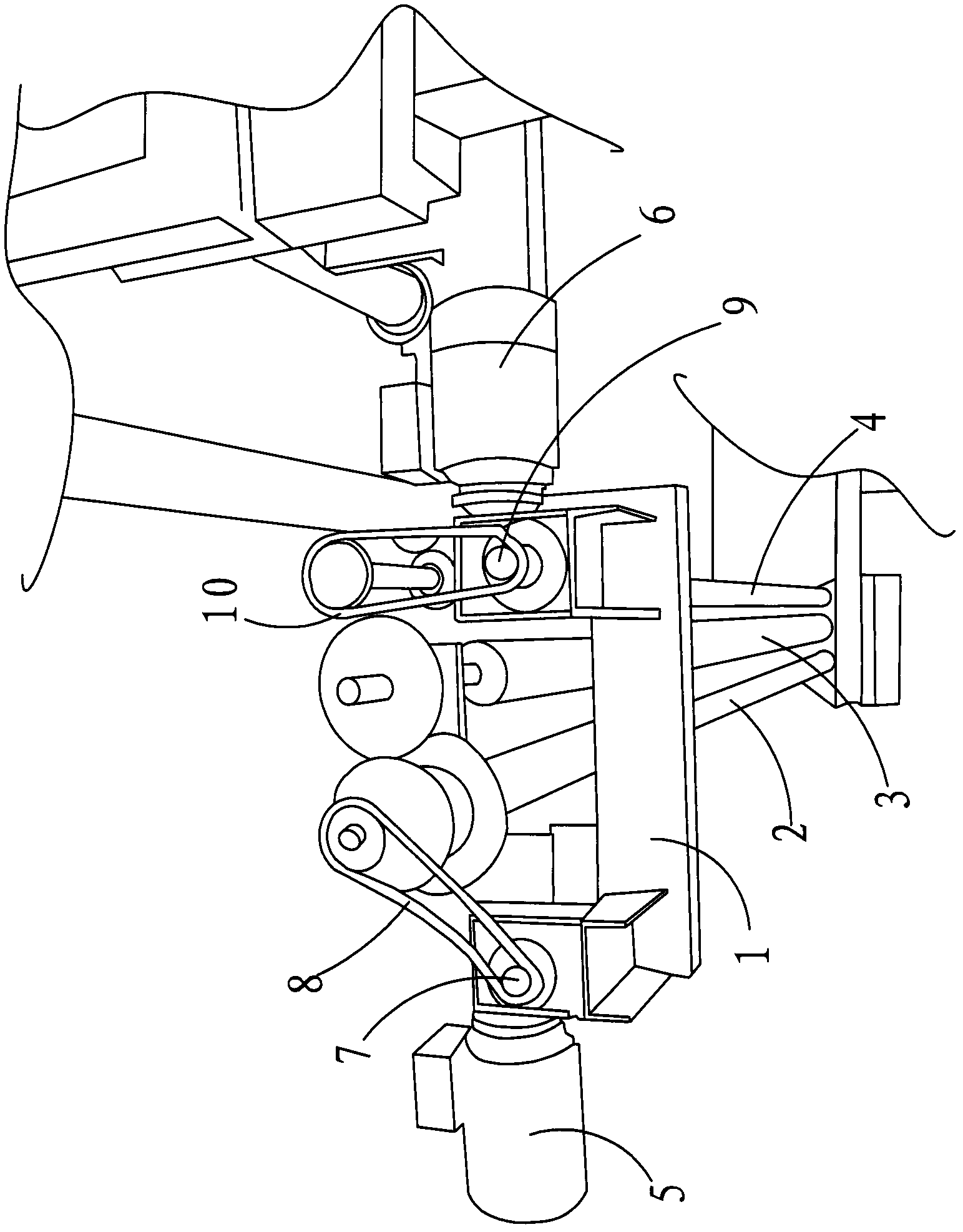
[0013] as attached figure 1 As shown, a control tension mechanism of a loom includes a first rod 2, a second rod 3, and a third rod 4 that are set in rotation with the frame 1, and drive the first rod 2 The first drive motor 5 that rotates with the second rod 3 and the second drive motor 6 that drives the third rod 4 rotate, and the knitting thread used for weaving passes around the first rod in turn 2, the second rod 3, the third rod 4, a transmission mechanism is arranged between the first rod 2 and the second rod 3, the first The rotation direction of the rod 2 is the same as that of the second rod 3 , and the rotation direction of the first rod 2 is opposite to that of the third rod 4 .

[0014] as attached figure 1 As shown, the first rod 2 , the second rod 3 , and the third rod 4 are parallel.

[0015] as attached figure 1 As shown, the first drive motor 5 has a first motor shaft 7 , and the first motor shaft 7 is connected to the first rod 2 through a first pulley 8...


PUM


Abstract

The invention discloses a controlled tension mechanism for looms. The controlled tension mechanism comprises a first bar, a second bar and a third bar, which are arranged in a way of rotating relative to a frame; a first driving motor which drives the first and the second bars to rotate; a second driving motor which drives the third bar to rotate; knitting yarns which are used for weaving and go around the first, the second and the third bars in sequence; and a transmission mechanism arranged between the first and the second bars. The rotation direction of the first bar is the same as that of the second bar, and the rotation direction of the first bar is opposite to that of the third bar. The controlled tension mechanism is applied to ensure better weaving effects.

Description

technical field [0001] The invention relates to a tension control mechanism of a loom. Background technique [0002] In the prior art, the loom is usually not provided with a tension control mechanism, and the weaving effect is relatively poor. Contents of the invention [0003] The technical problem to be solved by the present invention is to provide a tension control mechanism for a loom. [0004] In order to solve the above-mentioned technical problems, a technical solution adopted by the present invention is: a control tension mechanism of a loom, comprising a first rod, a second rod, a third rod, a The first drive motor that drives the first rod and the second rod to rotate, the second drive motor that drives the third rod to rotate, and the knitting thread for weaving goes around the The first rod, the second rod, and the third rod, a transmission mechanism is arranged between the first rod and the second rod, and the first rod The rotation direction of the first ...

Claims


Application Information

Patent Timeline
IPC IPC(8): D04B15/44D04B27/12
Inventor 胡永明
Owner SUZHOU HUALONG KNITTING TEXTILE
Why Eureka
Try Eureka