Reamer
A technology of eye reamer and expander, which is applied in the direction of earthwork drilling, drill bits, drilling equipment, etc., and can solve the problems that cannot fully meet the needs, the sealing structure is unreasonable, and the diameter of the reamer can not be enlarged.
- Summary
- Abstract
- Description
- Claims
- Application Information
AI Technical Summary
Problems solved by technology
Method used
Image
Examples
Embodiment 1
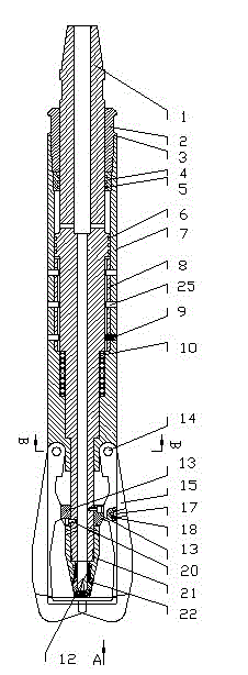
[0051] An eye reamer, including an outer cylinder 7 and a blade mechanism, and also includes a transmission shaft mechanism arranged in the outer cylinder 7 and sliding axially along the outer cylinder 7, and a reset mechanism for resetting the transmission shaft mechanism. The upper end of the outer cylinder 7 is A first sealing structure that cooperates with the outer wall of the transmission shaft mechanism to seal is provided, a blade groove 26 is provided at the lower end, a second sealing structure is provided at the end of the outer cylinder 7, the blade mechanism is arranged in the blade groove 26, and the transmission shaft mechanism An expander that drives the blade mechanism to expand outward is arranged on the top, and the inner cavity of the transmission shaft mechanism communicates with the blade groove 26 .
[0052] In the present invention, the blade mechanism includes a main blade 15 and an auxiliary blade 16, the main blade 15 is two with the same structure, a...
Embodiment 2
[0068]The outer cylinder 7 is a cylindrical structure, and the lower end of the cylinder has a blade groove 26 and a blade pin hole 27 connecting the main blade 15 and the auxiliary blade 16, and the main blade 15 and the auxiliary blade 16 are connected by the blade pin hole 27. In the blade groove 26, the rear end of the outer cylinder 7 has an end cap groove 28, and the assembled end cap 2 is arranged in the end cap groove 28, and a fixed sleeve 4 is arranged at the front end of the end cap 2, between the fixed sleeve 4 and the A fixed sleeve sealing ring 5 is arranged between the transmission shafts 1; a pin hole 25 and a spring groove 24 are arranged in the middle section of the outer cylinder 7. After assembling the present invention, the outer cylinder 7 and the fixed sliding sleeve 8 are fixed by the connecting pin 9 through the pin hole 25 The lower end of the transmission shaft 1, namely the reaming end, is provided with a cam groove 30 and a runner 29, the cam groove...
Embodiment 3
[0072] The assembly sequence of the present invention is:
[0073] Install the return spring 10 in the direction of the internal thread of the outer cylinder 7, and then put in the fixed sliding sleeve 8. The fixed sliding sleeve 8 is in the shape of an outer circle and an inner octagonal shape. The outer octagonal structure of the fixed shaft 11 matches the inner octagonal structure of the fixed sliding sleeve 8. Install the outer cylinder seal ring 6 on the transmission shaft 1, after the fixed sleeve seal ring 5 is installed on the fixed sleeve 4, the transmission shaft 1 is put into the outer cylinder 7 from the direction of the inner thread of the outer cylinder 7, and on the end surface of the inner thread of the outer cylinder 7 Place gasket 3, then put into end cap 2, end cap 2 is threadedly connected with outer cylinder 7, then put connecting pin 9 into pin hole 25.
[0074] Four cam blocks 13 are respectively installed in the cam grooves 30 on the four faces of the l...
PUM
 Abstract
Description
Claims
Application Information
 - R&D
- Intellectual Property
- Life Sciences
- Materials
- Tech Scout
- Unparalleled Data Quality
- Higher Quality Content
- 60% Fewer Hallucinations
Browse by: Latest US Patents, China's latest patents, Technical Efficacy Thesaurus, Application Domain, Technology Topic, Popular Technical Reports.
© 2025 PatSnap. All rights reserved.Legal|Privacy policy|Modern Slavery Act Transparency Statement|Sitemap|About US| Contact US: help@patsnap.com


