Rail wheel synchronous control device for rail transit vehicle traction power test device

A rail transit vehicle, synchronous control technology, applied in railway vehicle testing, non-electric variable control, and simultaneous control of multiple variables, etc., can solve problems such as difficulty, large reactive power, damage to synchronous gearboxes, and eliminate data loss. , to achieve the effect of synchronous control and stable synchronous control

Inactive Publication Date: 2017-03-15
北京鹏发欣光电力电子科技有限公司
View PDF4 Cites 0 Cited by
  • Summary
  • Abstract
  • Description
  • Claims
  • Application Information

AI Technical Summary

Problems solved by technology

However, this control method also needs to rely on external equipment to ensure the consistency of the shafting speed.
[0006] The third mode is to completely rely on the control accuracy of the converter to the load motor to ensure the consistency of the speed of all shaft systems. This control mode is the same as the locomotive shaft control mode, but it is synchronized. difficulty
The general idea is to exchange the information of the motor speed controlled by each converter through the high-speed communication between the converters, so as to achieve the consistency of the motor speed controlled by the converters. However, this method has certain disadvantages, that is, when the communication Lost, or when the communication is interrupted, the synchronization of all motor speeds cannot be guaranteed
[0007] From the above description, it can be known that the existing independent locomotive control has the following disadvantages: 1. In the first method, the synchronous gearbox bears the torque generated by the deviation of the motor speed, which is easy to cause damage to the synchronous gearbox
2. In the second method, the cost of the entire electric shaft system is high, and it generates a large amount of reactive power, polluting the power grid, and its synchronization effect is affected by the difference in motor parameters
3. The third method uses high-speed communication between the converters to complete the consistency of the speed of the converters to control the motor speed. This method relies heavily on communication reliability and speed, and cannot guarantee all motors in harsh electromagnetic environments. Synchronization of speed
This will cause the following problems: each motor controller self-tests its own speed, and the speed difference between the motors cannot be corrected quickly, and in severe cases, the deviation between each other will become larger and larger
2. It is impossible to realize the dynamic synchronization among the shaft systems

Method used


Image

  • Rail wheel synchronous control device for rail transit vehicle traction power test device
  • Rail wheel synchronous control device for rail transit vehicle traction power test device
  • Rail wheel synchronous control device for rail transit vehicle traction power test device

Examples


Embodiment Construction

[0026] The technical solutions of the present invention will be further described below in conjunction with the accompanying drawings and through specific implementation methods.

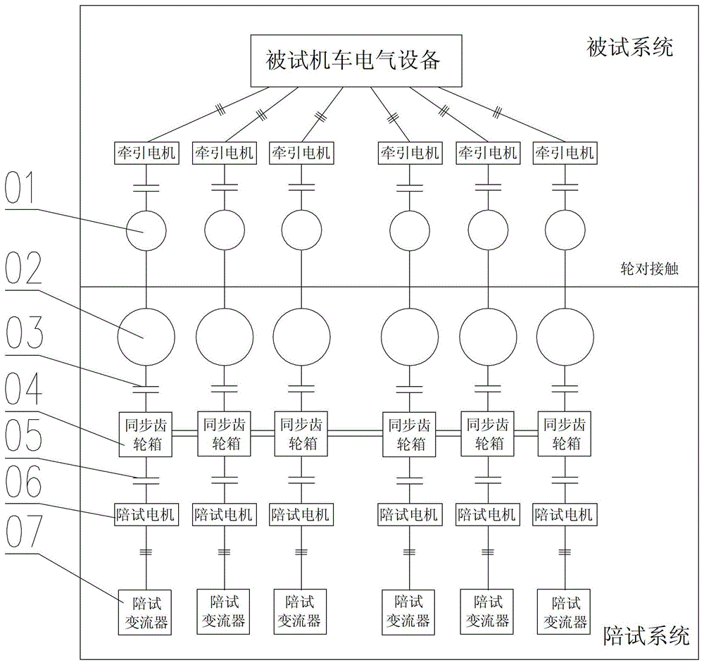
[0027] figure 1 It is a structural schematic diagram of the track wheel synchronous control device of the electric locomotive test bench in the prior art. Such as figure 1 As shown, the connection mode of the existing locomotive rail transit vehicle traction power test device is: each locomotive wheel 01 is in contact with the rail wheel 02 on the test bench, and the rail wheel 02 is connected with the synchronous gearbox 04 through the mechanical coupler 03 , the synchronous gearbox 04 is connected with the test motor 06 through the mechanical coupler 05, and the other end of the test motor 06 is connected with the test converter 07 for controlling it. The six synchronous gearboxes 04 are connected through shafts, and the synchronous gearbox 04 connects the shafting of all rail wheels 02, so that...


PUM


Abstract

The invention discloses a rail wheel synchronous control device for a traction power test device of a rail transit vehicle. An accompanying test motor is connected to one side of each rail wheel; a sensor is arranged between each rail wheel and an output shaft of each accompanying test motor; an accompanying test converter is connected to each accompanying test motor and is connected with a signal acquisition control unit arranged on the field; the signal acquisition control units are one or more circuit boards or circuit units arranged inside the accompanying test converters or signal acquisition controllers arranged outside the accompanying test converters; and the signal acquisition control units are used for receiving control signals from the sensors and / or other signal acquisition control units, and the control signals are integrally processed and then are outputted to the accompanying test converters. Dynamic work conditions of various motors are acquired on field in real time and are integrally processed by the signal acquisition control units for controlling various accompanying test converters, so that output rotating speeds and the torques of all motors can be enabled to be same, traction and brake work conditions of tested locomotives can be dynamically adapted and the synchronous control on the rail wheels can be realized more accurately.

Description

technical field [0001] The invention relates to a rail wheel synchronous control device, and more specifically, to a rail wheel synchronous control device for a traction power test device of a rail transit vehicle. Background technique [0002] At present, Harmony electric locomotives adopt axle control mode to control the traction or braking of the locomotive. When this control mode is running on the main line of the railway, since the rail is a whole straight line, it can ensure that the speed of all axles of the locomotive remains consistent, thus The tractive force of all axles of the locomotive is kept relatively balanced. However, during the vehicle test bench test, due to the characteristics of the mechanical structure of the test bench, the track wheels corresponding to each wheel pair of the locomotive are independent discs. If all the track wheels cannot maintain consistent operation, they cannot be like steel rails. By itself, all axles of the locomotive maintain...

Claims


Application Information

Patent Timeline
Patent Type & Authority Patents(China)
IPC IPC(8): G05D27/02G01M17/08
Inventor 张士光宋加旺郑立纹
Owner 北京鹏发欣光电力电子科技有限公司
Why Eureka
Try Eureka