
Parallel composite tank

A composite tank and powder storage technology, which is applied in fire rescue and other directions, can solve the problems of dry powder limitation, uneven mixing of dry powder and gas, and the amount of dry powder cannot meet the fire extinguishing requirements, so as to overcome the delay of fire extinguishing timing and reduce the influence of gravity. Effect

Active Publication Date: 2012-02-15
江苏中瑞电保智能装备有限公司
View PDF5 Cites 7 Cited by
  • Summary
  • Abstract
  • Description
  • Claims
  • Application Information

AI Technical Summary

Problems solved by technology

[0004] Traditional dry powder fire extinguishers are generally portable and cart-type, which have a powder storage tank for storing dry powder and power gas. On the one hand, because it is easy to carry or push, the volume of the powder storage tank is limited. The amount of dry powder is limited. For large-scale fires, the amount of dry powder in traditional fire extinguishing devices cannot meet the fire extinguishing requirements. On the other hand, since the power gas and dry powder are in a powder storage tank, when the valve is opened, only one fire extinguishing process can be formed. When the extinguished fire re-ignites, it cannot be extinguished again, and there are certain limitations in use
[0005] The dry powder and power gas of the traditional dry powder fire extinguisher are stored in the same tank. The dry powder fire extinguisher prevents that after a long time, the dry powder will be deposited on the bottom of the tank under the action of gravity. When the fire needs to be extinguished, the dry powder sprayed by the dry powder fire extinguisher and Uneven gas mixing, poor fire extinguishing effect

Method used


Image

  • Parallel composite tank
  • Parallel composite tank
  • Parallel composite tank

Examples


Embodiment Construction

[0028] The present invention will be further described below in conjunction with accompanying drawing:

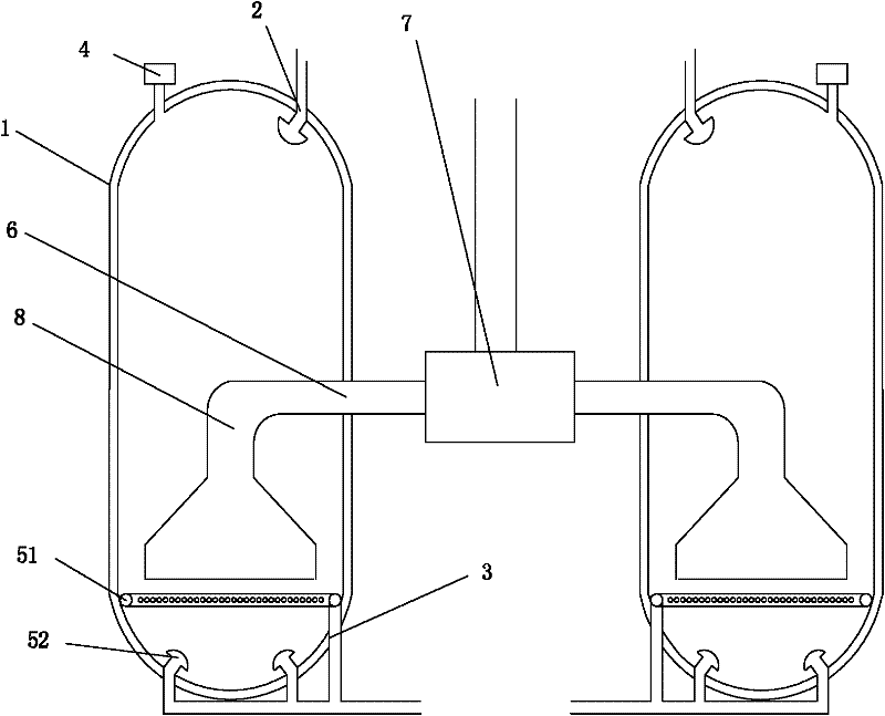
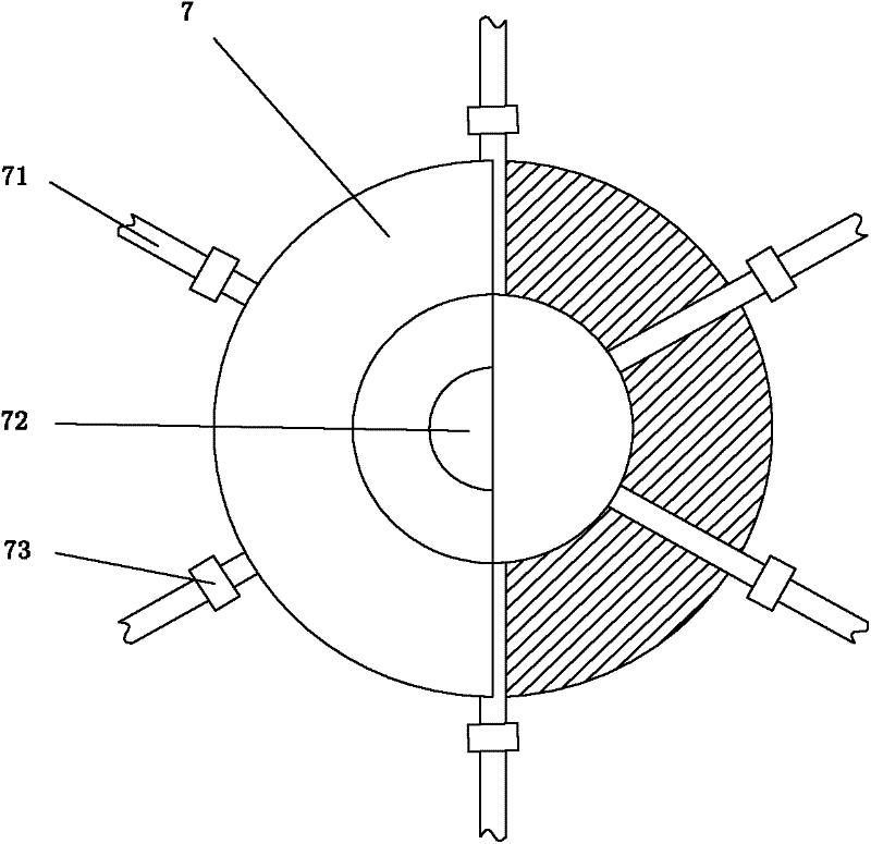
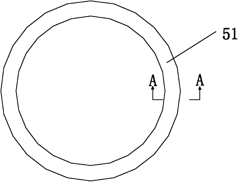
[0029] Such as Figure 1 to Figure 5 The parallel composite tank shown includes at least two powder storage tanks 1 for storing dry powder and capable of atomizing and mixing the dry powder in the tank. In this embodiment, two powder storage tanks are used for illustration. The two powder storage tanks 1 are arranged on the same horizontal line, which can reduce the influence of gravity on the dry powder airflow and ensure that the dry powder airflow output by the centralized controller of the dry powder pipeline is uniform. The top and bottom of the powder storage tanks An upper air inlet 2 and a lower air inlet 3 are provided. The top of the powder storage tank 1 is also provided with a pressure sensor 4 for detecting the pressure in the tank. The inside of the powder storage tank 1 is provided with a device for loosening and drying the dry powder. Atomized atomizing dev...


PUM


Abstract

The invention belongs to the field of fire-fighting fire extinguishing apparatus and especially relates to a parallel composite tank for fire extinguishing of large-scale equipment. The parallel composite tank comprises at least two powder storage tanks, which are for storing, atomizing and mixing dry powder and are in a same horizontal line; an upper air inlet and a lower air inlet are arranged on the top and the bottom of each powder storage tank; a pressure sensor for detecting pressure in each tank is arranged on the top of each powder storage tank; an atomizing device for loosening and atomizing the dry powder is arranged in each powder storage tank; the lower air inlet is connected with the atomizing device; a powder outlet is arranged on a side wall of each powder storage tank; and powder outlets of the at least two powder storage tanks are connected with a dry powder pipeline centralized controller through a connecting pipe. According to the invention, a plurality of powder storage tanks are connected through the dry powder pipeline controller, so as to start different numbers of powder storage tanks, according to fire behavior, to guarantee the amount of dry powder needed by fire extinguishing.

Description

technical field [0001] The invention belongs to the field of fire-fighting equipment, in particular to a parallel composite tank used for fire-extinguishing of large-scale equipment. Background technique [0002] Fire has a major impact on people's production and life as well as economic development. Therefore, in the field of fire fighting equipment, the fire fighting equipment room is an indispensable equipment. [0003] Common fire extinguishing equipment includes fire hydrants, carbon dioxide fire extinguishers and dry powder fire extinguishers. Fire hydrants are mainly used for fire extinguishing in buildings, using water as the fire extinguishing medium, which is not suitable for some power stations or oil depots, and its scope of use is relatively limited; It is also not suitable for use in power stations; the dry powder fire extinguisher uses the inorganic salts and volatile decomposition products in the dry powder to chemically inhibit and side-catalyze the free rad...

Claims


Application Information

Patent Timeline
Patent Type & Authority Applications(China)
IPC IPC(8): A62C35/02
Inventor 赵明洁凌文祥张科
Owner 江苏中瑞电保智能装备有限公司
Learn More