Supercharge Your Innovation With Domain-Expert AI Agents!

Gearbox in turbomachine

A technology of turbine engine and gearbox, which is applied in the direction of engine manufacturing, engine components, engine functions, etc., and can solve problems such as the complexity of gearbox design

Active Publication Date: 2013-02-27
SN DETUDE & DE CONSTR DE MOTEURS DAVIATION S N E C M A
View PDF6 Cites 5 Cited by
  • Summary
  • Abstract
  • Description
  • Claims
  • Application Information

AI Technical Summary

Problems solved by technology

In addition, each bearing requires its own lubrication line, which further complicates the gearbox design

Method used


Image

  • Gearbox in turbomachine
  • Gearbox in turbomachine
  • Gearbox in turbomachine

Examples


Embodiment Construction

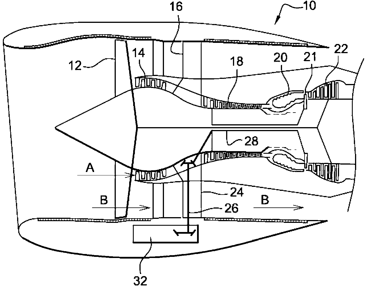
[0027] Referring first to FIG. 1 , there is shown a turbine engine 10 comprising, from upstream to downstream: a fan 12; a low pressure compressor 14; an intermediate casing 16; a high pressure compressor 18; a combustion chamber 20; a high pressure turbine 21; Turbine 22. The air entering the turbine engine is divided into primary airflow (arrow A) and secondary (bypass) airflow (arrow B), the primary airflow flows through the low pressure compressor 14 and the high pressure compressor 18 to the combustion chamber 20, and then flows through the high pressure turbine 21 and low pressure turbine 22, the secondary air flow flows around the compressors 14,18, the combustor 20 and the turbines 21,22.

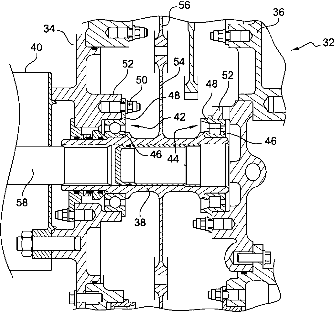
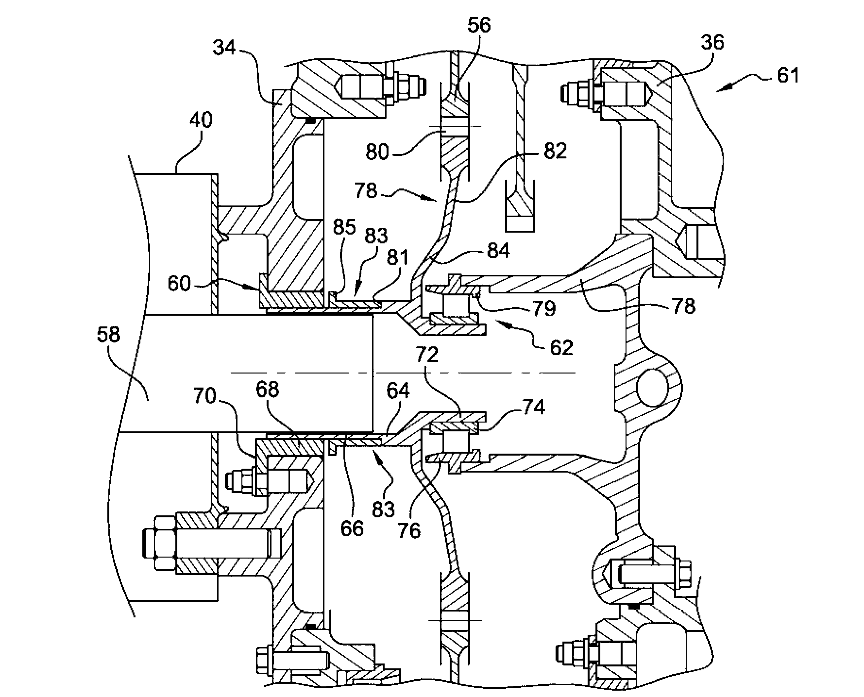
[0028] The intermediate housing 16 has structural arms 24 extending radially outwards. One of the structural arms 24 of the intermediate housing 16 includes a radial shaft 26 whose inner end is connected to a drive shaft 28 of the high pressure compressor 18 via a pair of bevel gea...


PUM


Abstract

Disclosed is a gearbox (61) in a turbomachine for rotatably driving at least one rotating device, comprising a transmission shaft that is rotatably guided in bearings (60, 62) and supports a toothed wheel (78) meshing with at least one rotatably driving pinion (56). One of the bearings is an antifriction bearing (62) that is mounted inside the toothed wheel (78) and contains the toothed wheel (78) and the driving pinion (56) on a radial plane, while another one of the bearings is a plain bearing (60) for absorbing tilting forces of the transmission shaft.

Description

technical field [0001] The present invention relates to gearboxes for providing rotational drive to equipment within turbine engines. Background technique [0002] In a turbine engine, various devices, such as, in particular, various pumps for generating hydraulic energy, delivering fuel, or providing lubrication, and generators for generating electricity, are driven to rotate through a gearbox connected to the shaft of the turbine engine. [0003] Each piece of equipment has a rotating shaft rotatably connected to the gearbox drive shaft. Each drive shaft has a gear on its exterior that meshes with a drive gear that is connected to the compressor shaft of the turbine engine through a gear train. [0004] The drive shaft is rotatably guided at its ends in two rolling bearings with fixed outer rings which are fixed by being fixed to the wall of the gearbox. [0005] In order to reduce the cost of the gearbox, people choose to use standardized bearings. As a result, the bea...

Claims


Application Information

Patent Timeline
IPC IPC(8): F01D15/10F16C21/00F01D15/08F01D15/12F02C7/32F01D25/16
CPCF01D15/08F05D2220/76F05D2260/4031F01D15/10F05B2240/52F02C7/32F01D25/166F01D15/12F05B2260/4031Y02T50/672F05B2240/53F05D2240/53F05D2250/313F05B2250/31F01D25/16F05B2250/313F05D2250/31F05D2240/52F16H1/04Y10T74/19642F16C19/54F16C21/00F16C2361/65Y02T50/60
Inventor 吉恩-皮埃尔·伊利·加利维尔
Owner SN DETUDE & DE CONSTR DE MOTEURS DAVIATION S N E C M A
Features
  • R&D
  • Intellectual Property
  • Life Sciences
  • Materials
  • Tech Scout
  • Unparalleled Data Quality
  • Higher Quality Content
  • 60% Fewer Hallucinations
Learn More