
Double diaphragm pump

A diaphragm pump and diaphragm technology, applied in the direction of pumps, pumps with flexible working elements, liquid displacement machinery, etc., can solve the problems of increasing pump maintenance costs, and achieve the effect of high service life and reliable switching

Active Publication Date: 2013-02-27
PROMERA
View PDF14 Cites 15 Cited by
  • Summary
  • Abstract
  • Description
  • Claims
  • Application Information

AI Technical Summary

Problems solved by technology

The disadvantage of the described pump is the large chamber that must be filled with compressed air after reaching the dead center, so that the diaphragm can move in the other direction
This requires an extremely large amount of compressed air, which increases the maintenance costs of the pump

Method used


Image

  • Double diaphragm pump
  • Double diaphragm pump
  • Double diaphragm pump

Examples


Embodiment Construction

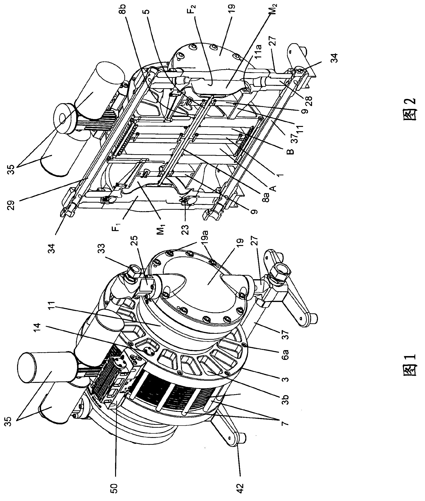
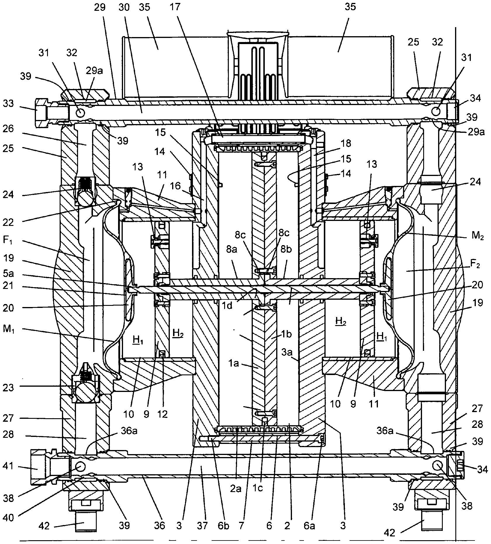
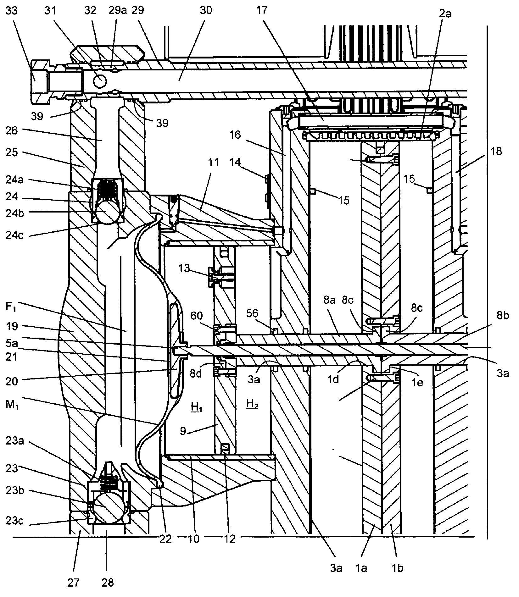
[0036] figure 1 and 2 A perspective view of a diaphragm pump according to the invention in the form of a double diaphragm pump is shown. The double-diaphragm pump has a housing cover 19 and a housing part 11 which accommodates the cylinder 10 of the hydraulically actuated piston-cylinder system 9 , 10 . as in figure 2 , the housing part 11 is fastened to the axial cylinder wall 3 of the first piston-cylinder system by means of coaxial screws 11a. by housing cover 19 and housing part 11 at 22 (see image 3 and 4 ) to clamp the diaphragm M. The housing cover 19 and the housing part 11 are connected to each other by means of bolts 19a and hold the membrane M in position. The housing cover 19 forms a receptacle for the check valve 24 below and above, respectively. The non-return valves 23 , 24 are inserted into corresponding recesses in the housing cover 19 before the housing flanges 25 , 27 are screwed onto the housing cover 19 . The additional seal prevents the delivery...


PUM


Abstract

The invention relates to a diaphragm pump, in which a fluid moves at least one first piston (1) of a first piston / cylinder system (1, 2, 3) to and fro, wherein the first piston (1) is mechanically connected to at least one further hydraulic piston (9), and the hydraulic piston (9) drives at least one diaphragm (M1, M2) by means of a hydraulic medium.

Description

technical field [0001] The invention relates to a diaphragm pump with at least one diaphragm. Background technique [0002] In a diaphragm pump, the diaphragm delimits the delivery chamber into which the input and discharge lines lead. Usually, non-return valves are provided in the supply line and the discharge line so that, by the reciprocating movement of the membrane, the conveying medium can be drawn in first into the conveying chamber via the supply line and can then be pressed out of the conveying chamber via the drain line. [0003] A continuous delivery is thus possible, usually two diaphragm pumps in parallel, wherein one of the diaphragm pumps sucks in the conveying medium and the other simultaneously presses the conveying medium out of its conveying chamber. [0004] Furthermore, double-diaphragm pumps are known, in which the diaphragms, which are usually designed as disc diaphragms, are adjusted by means of a common piston-cylinder system or by means of electric...

Claims


Application Information

Patent Timeline
Patent Type & Authority Applications(China)
IPC IPC(8): F04B43/02F04B43/073
CPCF04B43/073F04B43/026F04B43/06
Inventor 托马斯·许策
Owner PROMERA
Learn More