Powder storage container, powder conveying device, and image forming device
A technology of a conveying device and a storage container is applied in the direction of an electric recording process applying a charge pattern, equipment and instruments for an electric recording process applying a charge pattern, etc., and can solve the problems of not being able to send out the toner, and not being able to send all the toner out. , to achieve the effect of inhibiting poor powder conveying, powder conveying volume, and stable powder conveying
- Summary
- Abstract
- Description
- Claims
- Application Information
AI Technical Summary
Problems solved by technology
Method used
Image
Examples
no. 1 approach
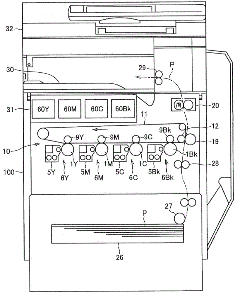
[0096] First, refer to figure 1 and figure 2 , Describe the overall structure and operation of the image forming apparatus. figure 1 It is a structural diagram showing a printer as an image forming apparatus, figure 2 It is an enlarged view showing the imaging part.
[0097] Such as figure 1 As shown, opposite to the intermediate transfer belt 11 of the intermediate transfer unit 10, image forming units 6Y, 6M, 6C, 6Bk corresponding to each color (yellow, magenta, cyan, and black) are arranged side by side. In addition, the four image forming units 6Y, 6M, 6C, and 6Bk provided in the main body 100 of the apparatus are basically the same in structure except for the toner used in the image forming process. figure 2 The letter marks (Y, M, C, Bk) in the image forming unit 6, the photosensitive drum 1, and the primary transfer bias roller 9 are omitted in the illustration.
[0098] Reference figure 2 The imaging unit 6 is composed of a photosensitive drum 1 as an image carrier, a ch...
no. 2 approach
[0209] Reference Figure 27 ~ Figure 33 , The second embodiment will be described in detail. In the second embodiment, the structure not specifically described is the same as that of the first embodiment.
[0210] In the prior art, there is known a developer supply device (see Japanese Patent Application Laid-Open No. 2005-91879). The developer supply device inserts a nozzle in a flexible container containing toner, and passes through the nozzle in the pump Under the action, the toner is sucked out and refilled to the developing device. In this toner replenishment method, as the toner is sucked out by the pump, the flexible container automatically reduces its volume. Then, in a state where there is almost no toner in the container, the container is in a squashed state, so it is possible to reduce the cost required for collection, transportation, and reuse of the used container. Furthermore, since the volume of the container is reduced according to the remaining toner amount in ...
no. 3 approach
[0241] Reference Figure 34 ~ Figure 38 , The third embodiment will be described in detail. In the third embodiment, the structure that is not particularly explained is the same structure as the first embodiment. According to Figure 34 ~ Figure 38 The specific structure of the vibration applying mechanism and the fixing portion provided with the vibration applying mechanism will be described.
[0242] Figure 34 Is a cross-sectional view of the fixed portion 63, Figure 35 Is a perspective view of the vibration applying mechanism, Figure 36 versus Figure 37 It is a perspective view of the fixed part.
[0243] Such as Figure 34 As shown, the fixed portion 63 is provided with an eccentric weight 93 attached to the rotating shaft as a vibration applying mechanism. And, as Figure 35 As shown, the eccentric weight 93 is a cylindrical member protruding to both sides in the axial direction, and an insertion hole 93a for inserting the rotating shaft is formed at a position deviated f...
PUM
 Abstract
Description
Claims
Application Information
 - R&D
- Intellectual Property
- Life Sciences
- Materials
- Tech Scout
- Unparalleled Data Quality
- Higher Quality Content
- 60% Fewer Hallucinations
Browse by: Latest US Patents, China's latest patents, Technical Efficacy Thesaurus, Application Domain, Technology Topic, Popular Technical Reports.
© 2025 PatSnap. All rights reserved.Legal|Privacy policy|Modern Slavery Act Transparency Statement|Sitemap|About US| Contact US: help@patsnap.com


