Multidirectional evacuating device for die-casting

A vacuum device and vacuum technology, applied in the field of casting, can solve the problems of limited storage capacity of the vacuum control unit, inconvenient storage of data, slow pumping speed, etc., to simplify the design process and mold structure, easy setting and maintenance, and long service life long effect

Inactive Publication Date: 2013-03-06
HUAZHONG UNIV OF SCI & TECH
View PDF8 Cites 41 Cited by
  • Summary
  • Abstract
  • Description
  • Claims
  • Application Information

AI Technical Summary

Benefits of technology

This patented technology describes various technical features for controlling the amount of air inside a chamber during manufacturing processes such as foundry operations. By measuring this quantity accurately and continuously, these technologies help improve production efficiency while reducing costs associated therewith.

Problems solved by technology

Technological Problem addressed in this patents relates to improving the efficiency and quality of producing high-quality metallic products such as those made up of materials like iron alloys due to their unique characteristics including low levels of voids within them. Current processes involve either slow down the process or require expensive equipment.

Method used


Image

  • Multidirectional evacuating device for die-casting
  • Multidirectional evacuating device for die-casting

Examples


Embodiment 1

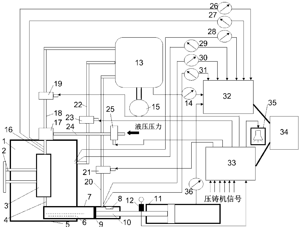
[0057] According to the high vacuum device and multi-directional vacuum device for die casting machine of the present invention, AlSi7Mg (impurity content in control alloy Fe<0.15%, Cu<0.05%) alloy is die-casted on a 2800KN horizontal cold chamber die-casting machine. First, make a good seal for the die-casting mold. The specific sealing method can use the existing sealing structure of the die-casting mold for high-vacuum pressure casting (Wuhan Engineering University proposed "a sealing structure for the die-casting mold for high-vacuum pressure casting" in 2007. (Publication number is CN201061825Y, publication date is 2008-05-21), the vacuum valve structure adopts a hydraulically driven vacuum valve, and then the AlSi7Mg alloy is melted, refined, and an appropriate amount of modifier and refiner is added, and the appropriate temperature is controlled to be poured 。At the same time, the mold is preheated to 150~200℃. Pour an appropriate amount of molten metal into the pressure ...

Embodiment 2

[0059] According to the high vacuum device and multi-directional vacuum device for die casting machine of the present invention, AlSi10Mg (the impurity content in the control alloy Fe<0.15%, Cu<0.05%) alloy is die-casted on a 2800KN horizontal cold chamber die-casting machine. First, the sealing structure of the die-casting mold for high-vacuum pressure casting can be used to seal the die-casting mold well. The vacuum valve structure adopts a hydraulically driven vacuum valve, and then the AlSi10Mg alloy is melted, refined, and appropriate modifiers and refiners are added to control The suitable temperature is to be poured. At the same time, the mold is preheated to 150~200℃. Pour an appropriate amount of molten metal into the injection chamber. The punch first slowly injects to seal the pouring port, and then vacuum starts. The pressure chamber, cavity and mold are three-way pumped. The vacuum pressure in the vacuum tank is below 10KPa. When the punch continues to move closer...


PUM

PropertyMeasurementUnit
Tensile strengthaaaaaaaaaa
Yield strengthaaaaaaaaaa

Abstract

The invention discloses a multidirectional evacuating device for die-casting, which comprises a vacuumizing unit and a vacuum control system. The vacuumizing unit comprises a vacuum pump, a vacuum tank, a cavity bleed-off passage, a pressure chamber bleed-off passage, die set bleed-off passages, a vacuum valve and electromagnetic valves; the cavity bleed-off passage is formed by a pipeline connected between the vacuum tank and the vacuum valve; the pressure chamber bleed-off passage is formed by a pipeline between the vacuum tank and a pressure chamber; each die set bleed-off passage is formed by a pipeline between the vacuum tank and a die set of a die-casting die; each die set bleed-off passage is provided with one electromagnetic valve; and the vacuum control system is used for acquiring information of each pressure sensor and each humidity sensor and switching on or switching off the corresponding electromagnetic valves according to external die-casting signals so as to switch on or switch off the corresponding bleed-off passages and control the vacuum degree of the die-casting die. According to the invention, the vacuumization is simultaneously carried out from three directions of a cavity, the pressure chamber and the die set; the evacuating rate and the evacuating efficiency are greatly improved; and an IPC (Industrial Personal Computer) is adopted to control, so that the high-speed dynamic response capacity and the data storage capacity of the detection are improved.

Description


Claims


Application Information

Patent Timeline
Owner HUAZHONG UNIV OF SCI & TECH
Why Eureka
Try Eureka