Supercharge Your Innovation With Domain-Expert AI Agents!

Spherical infrared sensor array direction finder

A technology of infrared sensor and direction finder, which is applied to the direction finder using electromagnetic waves, direction/deviation to determine the direction of the electromagnetic system, etc., can solve the problems that fire-fighting equipment cannot automatically determine the direction of the fire point, and monitoring equipment cannot automatically track the target. Achieve fast and accurate positioning

Inactive Publication Date: 2013-03-06
李良杰
View PDF7 Cites 2 Cited by
  • Summary
  • Abstract
  • Description
  • Claims
  • Application Information

AI Technical Summary

Problems solved by technology

[0002] At present, since there is no device that can automatically orient the person or object that emits infrared rays, the monitoring equipment often cannot automatically track the target object, and the fire fighting equipment usually cannot automatically determine the direction of the fire point

Method used


Image

  • Spherical infrared sensor array direction finder
  • Spherical infrared sensor array direction finder

Examples


Embodiment Construction

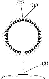
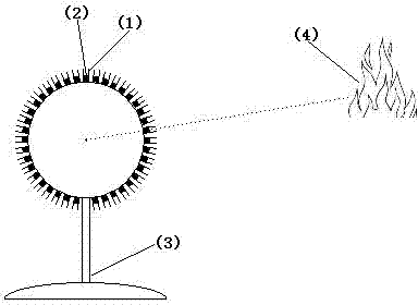
[0011] The spherical infrared sensor array orientation instrument consists of a spherical infrared sensor (2) array installed on the base (3) and a microcomputer module. Each infrared sensor is installed in a cylindrical tube (1) of the same size, and the cylindrical tubes are equidistant Evenly distributed on a spherical surface, the nozzle of the cylindrical tube is outward, and its center line points to the center of the sphere. The infrared sensor is installed at the bottom of the cylindrical tube, and its detection end is facing the nozzle. The signal input ends of the microcomputer modules are connected, and each infrared sensor corresponds to its coordinate on the spherical surface.

[0012] Each infrared sensor simultaneously transmits its own position coordinates and the intensity of the received infrared rays to the microcomputer module, and the microcomputer module finds the position coordinates of the sensor with the highest intensity of infrared rays received, and ...


PUM


Abstract

The invention relates to a spherical infrared sensor array direction finder, which consists of a spherical infrared sensor array and a microcomputer module, wherein the spherical infrared sensor array and the microcomputer module are arranged on a base, infrared sensors are respectively arranged on cylindrical tubes same in size, the cylindrical tubes are uniformly distributed on one sphere in equidistance, the openings of the cylindrical tubes face outwards, the centerlines of the cylindrical tubes point towards the center of sphere, the infrared sensors are arranged at the bottoms of the cylindrical tubes, the detection ends of the infrared sensors directly face the openings of the cylindrical tubes, a signal output line of each infrared sensor is respectively connected with a signal input end of the microcomputer module, and each infrared sensor is corresponding to the coordinate of the infrared sensor on the sphere. The position coordinate of each infrared sensor and the strength of the received infrared ray are simultaneously transmitted to the microcomputer module, the microcomputer module finds out the position coordinate of the infrared sensor with maximum infrared ray strength, and the direction to which the infrared sensor is pointed is the direction of a target object relative to the spherical sensor array.

Description

technical field [0001] The utility model relates to a spherical infrared sensor array orientation instrument. Background technique [0002] At present, since there is no device that can automatically orient the person or object that emits infrared rays, the monitoring equipment often cannot automatically track the target object, and the fire fighting equipment usually cannot automatically determine the direction of the fire point. Contents of the invention [0003] The invention provides a spherical infrared sensor array orientation instrument, which can automatically determine the direction of a person or object emitting infrared rays, and feed back the direction data to other devices so that they can perform corresponding operations. [0004] The technical solution adopted by the present invention to solve its technical problems is: the spherical infrared sensor array orientation instrument is composed of a spherical infrared sensor array and a microcomputer module insta...

Claims


Application Information

Patent Timeline
Patent Type & Authority Applications(China)
IPC IPC(8): G01S3/782
Inventor 李良杰
Owner 李良杰
Features
  • R&D
  • Intellectual Property
  • Life Sciences
  • Materials
  • Tech Scout
  • Unparalleled Data Quality
  • Higher Quality Content
  • 60% Fewer Hallucinations
Learn More