Method and device for transmitting reference signals
A technology of reference signal and transmission method, applied in the field of reference signal transmission method and device, can solve the problems that the reference signal cannot meet data demodulation requirements, system performance impact, etc., and achieve the effects of optimal communication performance and flexible transmission
- Summary
- Abstract
- Description
- Claims
- Application Information
AI Technical Summary
Problems solved by technology
Method used
Image
Examples
Embodiment 1
[0072] This embodiment describes the method for sending the second reference signal. Specifically, compared with the first reference signal, the density of the second reference signal is increased in the time domain, and the density of the second reference signal is the same as that of the first reference signal in the frequency domain.
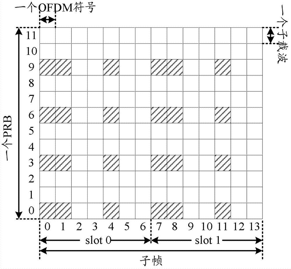
[0073] Such as Figure 5 As shown, in a downlink subframe, the subframe has a common CP length, and the second reference signal is transmitted in the 6th, 7th, 10th, 11th, 13th, and 14th OFDM symbols in a subframe, that is Figure 5 The second reference signal is transmitted in the 6 OFDM symbols numbered 5, 6, 9, 10, 12, and 13 respectively; as Figure 5 As shown, in one resource block, 3 subcarriers are occupied in the frequency domain to transmit the second reference signal corresponding to one port, and there are 4 subcarriers between two adjacent subcarriers among the 3 subcarriers.
[0074] Such as Figure 5 As shown, the second refer...
Embodiment 2
[0077] This embodiment describes the method for sending the second reference signal. Specifically, compared with the first reference signal, the density of the second reference signal is increased in the time domain, and the density of the second reference signal is the same as that of the first reference signal in the frequency domain.
[0078] Such as Figure 7 As shown, in the subframe of the downlink, the subframe has a common CP length, and the second reference signal, that is Figure 7 The second reference signal is transmitted in the 8 OFDM symbols numbered 2, 3, 5, 6, 9, 10, 12, and 13 respectively; as Figure 7 As shown, in one resource block, 3 subcarriers are occupied in the frequency domain to transmit the second reference signal corresponding to one port, and there are 4 subcarriers between two adjacent subcarriers among the 3 subcarriers.
[0079] Figure 7 The reference signal in includes two groups, represents the first group of second reference signals, ...
Embodiment 3
[0083] This embodiment describes the method for sending the second reference signal. Specifically, compared with the first reference signal, the second reference signal has a reduced density in the frequency domain and is the same as the first reference signal in the time domain density. Thus, the second The reference signal can be used for data demodulation when the channel coherence bandwidth is large.
[0084] Specifically, such as Figure 9 As shown, in the downlink subframe, the subframe has a common CP length, and the second reference signal is transmitted in the 6th, 7th, 13th and 14th OFDM symbols in a subframe, namely Figure 9 The second reference signal is transmitted in the 4 OFDM symbols numbered 5, 6, 12, and 13 respectively; for example Figure 9 As shown, the second reference signal includes two groups, represents the first group of second reference signals, Indicates the second group of second reference signals. Within one resource block, two subcarriers ...
PUM
 Abstract
Description
Claims
Application Information
 - R&D
- Intellectual Property
- Life Sciences
- Materials
- Tech Scout
- Unparalleled Data Quality
- Higher Quality Content
- 60% Fewer Hallucinations
Browse by: Latest US Patents, China's latest patents, Technical Efficacy Thesaurus, Application Domain, Technology Topic, Popular Technical Reports.
© 2025 PatSnap. All rights reserved.Legal|Privacy policy|Modern Slavery Act Transparency Statement|Sitemap|About US| Contact US: help@patsnap.com


