Sand-saving type sand box for manufacturing high-strength sand mould

A high-strength, sand box technology, applied in the direction of mold boxes, manufacturing tools, casting molding equipment, etc., can solve the problems of affecting the quality of sand castings, the weight of the sand box, and the deformation of sand molds, so as to avoid sand deformation or sand leakage pollution The effect of reducing the amount of ground and sand filling and improving the strength and bearing capacity

Active Publication Date: 2013-03-13
HENAN YUXING CASTING
View PDF7 Cites 0 Cited by
  • Summary
  • Abstract
  • Description
  • Claims
  • Application Information

AI Technical Summary

Problems solved by technology

[0002] Casting is an earlier metal thermal processing technology mastered by humans. It has a history of 6,000 years. Casting refers to melting solid metal into liquid and pouring it into a mold of a specific shape. After it is solidified and formed, it is obtained after cleaning. The process of castings with predetermined shape, size and performance. The sand box is commonly used in the casting process. The sand box is a part of the mold and is mainly used to accommodate and support the sand mold. The traditional sand box requires a large amount of sand filling, so that the sand The weight of the box becomes larger, and it is inconvenient to move, and the sand core head at the core mouth of the sand box is easy to collide with the sand box, resulting in damage to the core head. When the gap between the core head and the sand box is too large, it will cause the sand box to leak sand. Sand mold deformation affects sand mold and casting quality

Method used


Image

  • Sand-saving type sand box for manufacturing high-strength sand mould
  • Sand-saving type sand box for manufacturing high-strength sand mould
  • Sand-saving type sand box for manufacturing high-strength sand mould

Examples


specific Embodiment approach

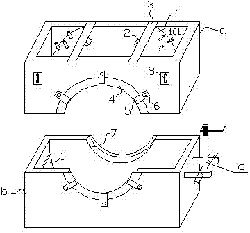
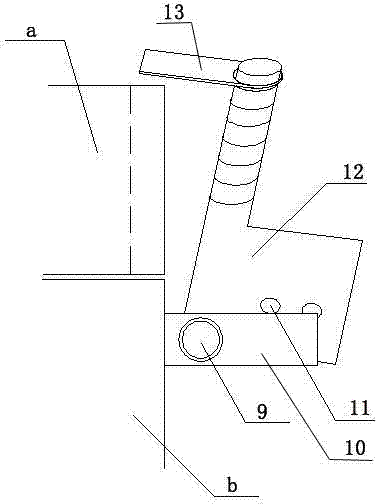
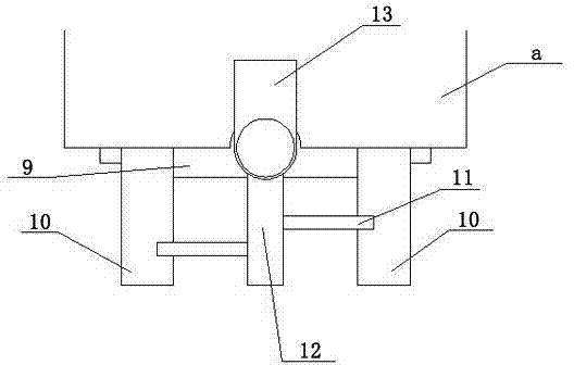
[0020] The specific embodiment of the present invention will be described below in conjunction with the accompanying drawings: a sand-saving sand box for manufacturing high-strength sand molds, including an upper box body a, a lower box body b and a sand box locking mechanism c, and the top of the upper box body a The bottom port of the lower box b is open, the sides of the upper box a and the lower box b are provided with core openings 7, and the upper box a and the lower box b are equipped with arc-shaped plates 1, arc-shaped plates The concave surface of 1 faces the center of the box body, and the two sides of the arc-shaped plate 1 are fixedly connected with the inner walls of both sides of the box body, and one end of the arc-shaped plate 1 is flush with the port of the box body, and is connected with the connection plate 3, The two ends of the two sides are respectively fixedly connected with the side walls on both sides of the box body. Strip keels 2 are provided on the ...

Embodiment 1

[0030] A sand-saving sand box for making high-strength sand molds, including an upper box body a, a lower box body b, and a sand box locking mechanism c. There are multiple sets of sand box locking mechanisms c, all of which are arranged on the side of the sand box , the top of the upper box a and the bottom port of the lower box b are open, the sides of the upper box a and the lower box b are provided with core openings 7, and the upper box a and the lower box b are equipped with arc Plate 1, the concave surface of the arc-shaped plate 1 faces the center of the box body, the two sides of the arc-shaped plate 1 are fixedly connected with the inner walls of both sides of the box body, and one end of the arc-shaped plate 1 is flush with the port of the box body and connected with the connecting plate 3 connection, the two ends of the connecting plate 3 are respectively fixedly connected with the side walls on both sides of the box body, strip keels 2 are provided on the concave s...

Embodiment 2

[0037] A sand-saving sand box for manufacturing high-strength sand molds, including an upper box body a, a lower box body b, and a sand box locking mechanism c. There are four sets of sand box locking mechanisms c, all of which are arranged on four sides of the sand box On one side, the top of the upper box a and the bottom port of the lower box b are open, the sides of the upper box a and the lower box b are provided with core openings 7, and the upper box a and the lower box b are provided with There is an arc-shaped plate 1, the concave surface of the arc-shaped plate 1 faces the center of the box body, the two sides of the arc-shaped plate 1 are fixedly connected with the inner walls of both sides of the box body, and one end of the arc-shaped plate 1 is flush with the port of the box body, and Connected with the connecting plate 3, the two ends of the connecting plate 3 are respectively fixedly connected with the side walls on both sides of the box, the concave surface of ...


PUM


Abstract

The invention relates to a sand-saving type sand box for manufacturing a high-strength sand mould. The sand-saving type sand box comprises an upper box body, a lower box body and a sand box locking mechanism, wherein ports in the top end of the upper box body and the bottom end of the lower box body are opened; core ports are formed in the side surfaces of the upper box body and the lower box body; arc-shaped plates are arranged in the upper box body and the lower box body; concave surfaces of the arc-shaped plates face to the centers of the box bodies; two sides of each arc-shaped plate are fixedly connected with inner walls of two sides of each box body; one end of each of the arc-shaped plates is aligned to the ports of the box bodies and connected with connecting plates; two ends of each connecting plate are fixedly connected with the sidewalls on the two sides of each box body; strip-shaped keels are arranged on the concave surfaces of the arc-shaped plates; sand baffle plates are arranged at the side edges of the core ports; and the sand baffle plates are connected to the sidewalls of the box bodies by a plurality of fixing sheets. By adopting of the sand-saving type sand box for manufacturing the high-strength sand mould, the weight of the sand box can be reduced, the sand leakage of the sand box can be prevented, and the production efficiency in casting process can be effectively improved.

Description

technical field [0001] The invention relates to a casting sand box, in particular to a sand-saving sand box used for manufacturing high-strength sand molds. Background technique [0002] Casting is an earlier metal thermal processing technology mastered by humans. It has a history of 6,000 years. Casting refers to melting solid metal into liquid and pouring it into a mold of a specific shape. After it is solidified and formed, it is obtained after cleaning. The process of castings with predetermined shape, size and performance. The sand box is commonly used in the casting process. The sand box is a part of the mold and is mainly used to accommodate and support the sand mold. The traditional sand box requires a large amount of sand filling, so that the sand The weight of the box becomes larger, and it is inconvenient to move, and the sand core head at the core mouth of the sand box is easy to collide with the sand box, resulting in damage to the core head. When the gap betwee...

Claims


Application Information

Patent Timeline
IPC IPC(8): B22C21/00B22C21/04B22C21/12B22C21/14
Inventor 付艮团王伟欣吴建祥焦好亮
Owner HENAN YUXING CASTING
Why Eureka
Try Eureka