Side-slit drip irrigation belt

A drip irrigation belt and edge seam technology, applied in the direction of spray device, spray device, etc., can solve the problems of short laying distance, insufficient, wet area formation, etc., and achieve the effect of increasing laying length, improving utilization rate and improving efficiency.

Inactive Publication Date: 2013-03-20
XINJIANG HUILI IRRIGATION TECH CORP
View PDF6 Cites 0 Cited by
  • Summary
  • Abstract
  • Description
  • Claims
  • Application Information

AI Technical Summary

Problems solved by technology

[0002] At present, in water-saving irrigation agriculture, most of the drip irrigation belts used in water-saving drip irrigation are single-channel, the flow rate is too large, and the distance between the drippers of the drip irrigation belts is also set relatively large, and the flow rate of the drippers is also relatively large. The minimum flow rate of the drippers is 2L. / h, because the flow rate is too large, the laying distance is too short, and the distance between the outlet piles is too small, which cannot achieve the purpose of agricultural modernization; at the same time, due to the excessive distance between the drippers of the drip irrigation belt, the outlet will form a blocky wet area during the work of the drip irrigation system , because in the actual agricultural production, the planting distance of the crops is not the same, so the wet area cannot be formed according to the actual water demand of the crops, so that the drip irrigation belt cannot be guaranteed to match the area to be wetted by the crops, resulting in water resources. The use is unreasonable and insufficient. Since the current mainstream of drip irrigation belts is single channel, from a technical point of view, it is impossible to make a flow rate of less than 2L / h

Method used


Image

  • Side-slit drip irrigation belt
  • Side-slit drip irrigation belt

Examples


Embodiment 1

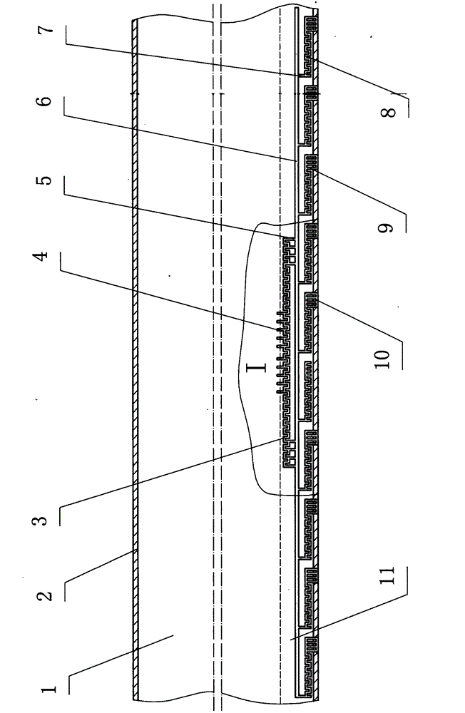
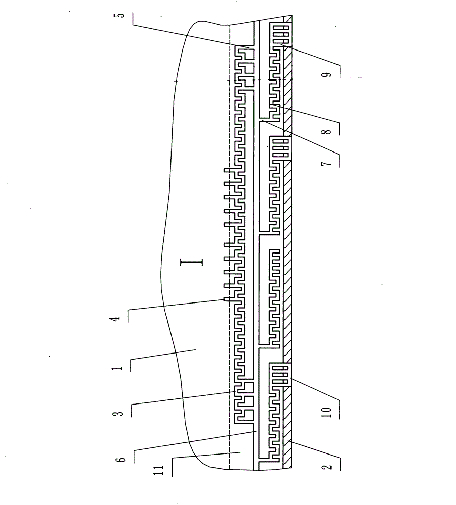
[0017] Embodiment 1: with reference to attached Figure 1~2 , comprising a drip irrigation tape body 2, a drip irrigation tape inner cavity 1 and a drip irrigation tape edge seam 10, the drip irrigation tape edge seam 10 is provided with a main channel 3, a secondary flow channel 8 and a buffer flow channel 6, and the main channel 3 is located at The side seam 10 of the drip irrigation belt is on the side of the inner chamber 1 of the drip irrigation belt, and the auxiliary flow channel 8 is arranged on the side of the side seam 10 of the drip irrigation belt near the side of the body 1 of the drip irrigation belt. Between the channel 3 and the secondary channel 8, the main channel 3 is provided with a main channel inlet 4 and a main channel outlet 5, the main channel inlet 4 communicates with the inner cavity 1 of the drip irrigation belt, and the main channel outlet 5 communicates with the buffer channel 6 , The secondary channel 8 is provided with a secondary channel inlet ...

Embodiment 2

[0018] Embodiment 2: Compared with Embodiment 1, the difference is that: the main channel 3 is in the shape of sawtooth "concave-convex" and is arranged continuously; the secondary channel 8 is in the shape of sawtooth "concave-convex" and is continuously arranged; There are six inlets 4, at least two outlets 5 of the main channel, two outlets 9 of the secondary channel, and one main channel unit and one auxiliary channel unit.

Embodiment 3

[0019] Embodiment 3: Compared with Embodiment 1, the difference is that: there are twelve main channel inlets 4, at least three main channel outlets 5, three secondary channel outlets 9, one main channel unit and It consists of twelve sub-runner units.


PUM


Abstract

The invention relates to a small-slit flow side-sewing slit drip irrigation belt. The side-sewing slit drip irrigation belt comprises a drip irrigation belt body, a drip irrigation belt inner cavity and a drip irrigation belt side- slit, wherein a main runner, an auxiliary runner and a buffering runner are arranged inside the drip irrigation belt side slit, the main runner is arranged on one side of the drip irrigation belt side slit to bewhich is close to the drip irrigation belt inner cavity, the auxiliary runner is arranged on one side of the drip irrigation belt side slit to bewhich is close to the drip irrigation belt body, the buffering runner is arranged between the main runner and the auxiliary runner inside the drip irrigation belt side slit, the main runner is provided with a main runner entrances and a main runner exits, the main runner entrances is are communicated with the drip irrigation belt inner cavity, the main runner exits is are communicated with the buffering runner, the auxiliary runner is provided with an auxiliary runner entrances and an auxiliary runner exits, the auxiliary runner entrances is are communicated with the buffering runner, and the auxiliary runner exits leads to the outside of the drip irrigation belt body. Due to the adoption of the side-slit drip irrigation belt, a slender moistening zone can be formed, the moistening zone can guarantee the reasonability in use of water for crops, the utilization rate of the water resource is greatly increased, the side-slit drip irrigation belt is applicable to the drip irrigation of multiple crops, and an important significance on popularizing the automatic irrigation technology can be realized.

Description

technical field [0001] The invention relates to an agricultural water-saving drip irrigation belt, in particular to a side seam type drip irrigation belt. Background technique [0002] At present, in water-saving irrigation agriculture, most of the drip irrigation belts used in water-saving drip irrigation are single-channel, the flow rate is too large, and the distance between the drippers of the drip irrigation belts is also set relatively large, and the flow rate of the drippers is also relatively large. The minimum flow rate of the drippers is 2L. / h, because the flow rate is too large, the laying distance is too short, and the distance between the outlet piles is too small, which cannot achieve the purpose of agricultural modernization; at the same time, due to the excessive distance between the drippers of the drip irrigation belt, the outlet will form a blocky wet area during the work of the drip irrigation system , because in the actual agricultural production, the p...

Claims


Application Information

Patent Timeline
Patent Type & Authority Applications(China)
IPC IPC(8): B05B1/20B05B1/30
Inventor 门旗尹强周莉薇李将
Owner XINJIANG HUILI IRRIGATION TECH CORP
Why Eureka
Try Eureka