
Swell-shrink drawing molding process and device for reducing pipes

A forming process and technology of reducing tubes, applied in the direction of wire drawing dies, mandrels, etc., can solve the problems of inability to realize different-diameter tube drawing and processing of different-diameter tubes

Active Publication Date: 2013-03-20
CHONGQING XIZHONG SPECIAL ALUMINUM
View PDF8 Cites 0 Cited by
  • Summary
  • Abstract
  • Description
  • Claims
  • Application Information

AI Technical Summary

Problems solved by technology

When the cold drawing process is used to draw the pipe, it can only be drawn with a single diameter, and the drawing of the pipe with different diameters cannot be realized.
[0010] The process methods and equipment of the prior art cannot process relatively slender reducers

Method used


Image

  • Swell-shrink drawing molding process and device for reducing pipes
  • Swell-shrink drawing molding process and device for reducing pipes
  • Swell-shrink drawing molding process and device for reducing pipes

Examples


Embodiment Construction

[0037] Below in conjunction with accompanying drawing and embodiment the present invention will be further described:

[0038] A method for expanding and shrinking drawing and forming of different-diameter pipes, characterized in that: the process includes

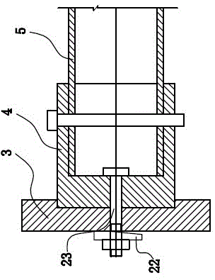
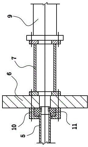
[0039] The first step of necking: install the pipe on the frame, one end of the pipe is fixed by the push seat, the middle part is supported by the protective sleeve installed on the support seat, and then the other end of the pipe is necked by the neck push head ;

[0040] The second step of annealing: annealing the necked pipe through the annealing device;

[0041] The third step of drawing: drawing the pipe processed in the second step through the drawing chuck to form a different-diameter pipe blank;

[0042] The fourth step of annealing: annealing the blank of the reducing pipe through the annealing device;

[0043] The fifth step is to expand the tube, sizing and wall thickness drawing: through the drawing chuck, ...


PUM


Abstract

The invention relates to metal pipe processing, in particular to a swell-shrink drawing molding process and a device for reducing pipes. The process comprises the following steps: Step 1, necking: a pipe is installed on a rack; one end of the pipe is fixed through a pushing seat, the middle part of the pipe is supported through a protective sleeve installed on a supporting seat, and then the other one of the pipe is necked through a necking and pushing head; Step 2, annealing: the necked pipe is annealed through an annealing device; Step 3, drawing: the pipe treated by the step 2 is drawn through a drawing chuck to form a reducing pipe blank; Step 4, annealing: the reducing pipe blank is annealed through the annealing device; and Step 5, sizing, determining wall thickness and drawing: the reducing pipe blank treated by the Step 4 is subjected to the sizing, determining wall thickness and drawing treatment through the drawing chuck to form a reducing pipe finished-product. Due to the structure, the process and the device have the advantages that the processing quality and precision of the reducing pipe is increased, and the production of relatively long and thin reducing pipes is realized.

Description

technical field [0001] The invention relates to metal pipe processing, in particular to an expansion-contraction drawing forming process and a device for improving the quality precision of different-diameter pipes and capable of producing relatively slender different-diameter pipes. Background technique [0002] The so-called reducer, commonly known as the big and small head, is a kind of pipe fitting used for pipe diameter reduction. The most widely used is on the pipelines of chemical plants. Usually divided into concentric reducer and eccentric reducer. The material of the reducer includes stainless steel reducer, alloy steel reducer, No. 20 rigid reducer, etc. [0003] There are national standards for reducers, such as "Steel Welded Seamless Pipe Fittings" GB / T12459-2005, "Steel Butt Welded Pipe Fittings" GB / T13401-2005 and so on. [0004] The diameter specifications of the reducer range from 25 (big head) * 15 (small head) to 1500 (big head) * 1200 (small head). The ...

Claims


Application Information

Patent Timeline
IPC IPC(8): B21C1/24B21C5/00B21C3/02B21C3/16
Inventor 刘选萍
Owner CHONGQING XIZHONG SPECIAL ALUMINUM
Learn More