
A kind of valve processing equipment and its processing technology

A technology for processing equipment and valve bodies, applied in metal processing equipment, turning equipment, turning equipment, etc., can solve the problems of low processing efficiency and inability to meet the needs of rapid processing, achieve high processing efficiency, improve processing quality accuracy, and improve The effect of the crumb effect

Active Publication Date: 2018-10-23
TAIZHOU HENGXIN METAL PROD FACTORY
View PDF9 Cites 0 Cited by
  • Summary
  • Abstract
  • Description
  • Claims
  • Application Information

AI Technical Summary

Problems solved by technology

[0003] To process the valve body of the above-mentioned type, the general structure of the equipment usually used is such as a Chinese utility model valve core processing device with the announcement number CN201900517U, which mainly includes a lathe, and the lathe is equipped with a clamping device, which can produce Circumferential rotation, a tool seat is also set on the lathe, and the tool seat also slides left and right along the lathe; the valve body of the stop valve is clamped on the clamping device, and the first water channel 4 to be processed must deviate from the first The crossing of the second branch pipe 5 or the second branch water channel 6 is away from the crossing of the first branch pipe 3 and faces the knife seat for further processing; because there are at least two openings to be processed in this type of shut-off valve body, that is, the first branch The waterway 4 is away from the crossing of the second branch pipe 5 or the second branch waterway 6 is away from the crossing of the first branch pipe 3. Even if the above-mentioned processing device is used, after one of the mouths is processed, the stop valve body needs to be disassembled, and the entire cut-off valve needs to be rotated. The valve body is installed on another processing equipment with the other mouth facing the tool seat; the processing efficiency is extremely low and cannot meet the needs of rapid processing

Method used


Image

  • A kind of valve processing equipment and its processing technology
  • A kind of valve processing equipment and its processing technology
  • A kind of valve processing equipment and its processing technology

Examples


Embodiment 1

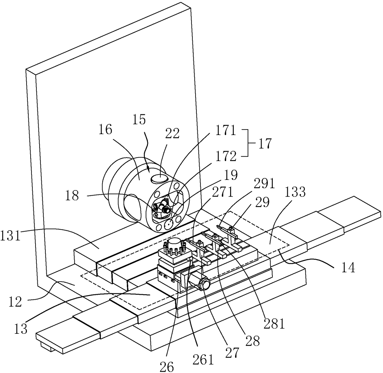
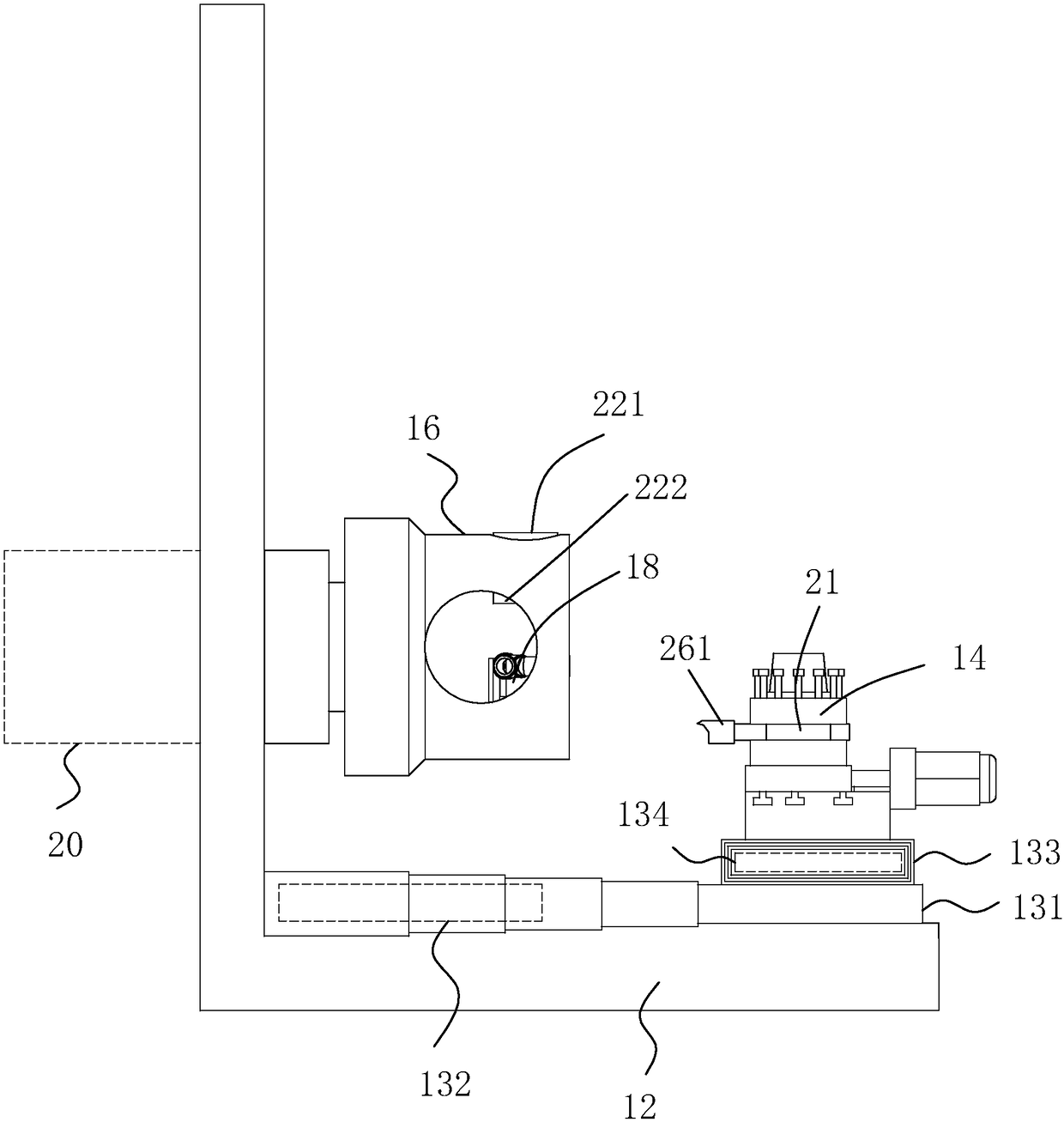
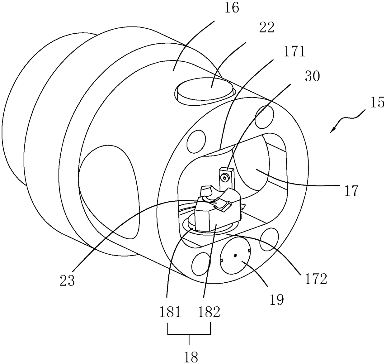
[0054] A kind of valve processing equipment, see figure 1 as well as figure 2 As shown, the bed body 12 is included, the bed body 12 includes a horizontal plane and a vertical plane, and a mobile platform group 13 is installed on the horizontal plane of the bed body 12, and the mobile platform group 13 can realize horizontal and vertical two-way sliding actions ,, and on the upper end surface of the longitudinal moving table 133, a tool holder group 14 is provided, on which a processing tool 21 is installed; on the vertical surface of the bed body 12, a clamping part 15 and a driving part 20 , the connection relationship between the clamping part 15 and the vertical surface of the bed body 12 is a rotary connection, the driving part 20 can be a rotary motor, and the driving part 20 can directly drive the clamping part 15 to rotate in a circumferential direction, and the clamping part 15 The axis of rotation of the center of rotation is in the horizontal direction. The clamp...

Embodiment 2

[0063] Embodiment 2: The difference from Embodiment 1 is that, see Figure 8 As shown, the telescopic power part 22 uses a push rod linear motor 223 instead, and the connection mode between the motor housing of the push rod linear motor 223 and the upper groove wall 171 is a rotary connection, and the push rod end of the push rod linear motor 223 is also the same There is a pressing block 222 for contact with the valve body to be processed, and the rotation axis of the push rod linear motor 223 is consistent with the rotation axis of the installation table 18; the push rod linear motor 223 can drive the push rod end to perform up and down telescopic movement , the pressing block 222 at the end presses the valve body to be processed on the installation platform 18, when the installation platform 18 rotates, because the push rod linear motor 223 is connected to the upper groove wall 171 in rotation, the push rod linear motor 223 Smooth rotation occurs.

Embodiment 3

[0064] Embodiment three: a kind of processing technology, comprises the following steps:

[0065] S1: Preliminary clamping and alignment. The valve body to be processed is placed on the installation platform 18 and pressed by the telescopic power part 22. The symmetrical point 7 in the valve body is located on the rotation axis of the installation platform 18, and the second branch pipe of the valve body The pipe end of 5 is facing the opening of the clamping groove 17;

[0066] S2: The polished turning tool 261 on the first tool seat 26 is close to the end of the second branch pipe 5, and the outer side of the end of the second branch pipe 5 is polished, thereby effectively reducing the roughness of the outer wall of the second branch pipe 5 end ;

[0067] S3: the external thread turning tool 271 on the second tool seat 27 processes the external thread section 11 at the end of the second branch pipe 5 with a relatively low roughness;

[0068] S4: secondary clamping and alig...


PUM


Abstract

The invention discloses machining equipment for valves, and a machining process thereof. The essential of the technical scheme is as follows: the machining equipment comprises a bed body, a movable table group, a clamping part, and a drive part used for driving the clamping part to circumferentially rotate, wherein a tool apron group is arranged on the movable table group, and a machining tool is arranged on the tool apron group; and the clamping part comprises a clamping sleeve, a clamping groove with an opening facing the tool apron group is formed in the clamping sleeve, the clamping groove comprises an upper groove wall and a lower groove wall which are oppositely arranged, a telescopic power element is rotationally connected to the upper groove wall, and an installation table and a rotary drive element are rotationally connected to the lower groove wall. The machining equipment realizes single workpiece clamping, plays a role of machining the end parts of a plurality of branch pipes, and achieves extremely high machining efficiency, and the machined valve body is high in quality and accuracy due to no need of secondary clamping; and the circumferential rotation force of the installation table is reasonably used for driving an air-blowing nozzle to synchronously rotate with the installation table, so that the chip removal effect of the air-blowing nozzle for the interior of a valve body is specifically improved, and further improvement for the machining quality and accuracy of the valve body is promoted.

Description

technical field [0001] The invention relates to valve processing equipment, in particular to valve processing equipment and a processing technology thereof. Background technique [0002] The common globe valve body structure is as follows: Figure 9 As shown, it includes a main pipe 1, a first branch pipe 3, and a second branch pipe 5. The first branch pipe 3 and the second branch pipe 5 intersect at a symmetrical point 7, the main pipe 1 intersects the first branch pipe 3, and a main waterway 2 is arranged inside the main pipe 1. , the first branch pipe 3 is provided with a first branch waterway 4, the second branch pipe 5 is provided with a second branch waterway 6, the main waterway 2, the first branch waterway 4, and the second branch waterway 6 are connected; A reinforcement sleeve 8 is provided on the outer wall of a pipe 3, and the reinforcement sleeve 8 is used to strengthen the connection strength between the first branch pipe 3 and the main pipe 1; an internal thre...

Claims


Application Information

Patent Timeline
Patent Type & Authority Patents(China)
IPC IPC(8): B23B5/06
CPCB23B5/06
Inventor 张文金郑妙福马超
Owner TAIZHOU HENGXIN METAL PROD FACTORY
Learn More