Yarn releasing roll mechanism

A technology of yarn roller and roller shaft, which is applied in the field of mechanical parts to achieve the effect of precisely controlling the amount of yarn released

Inactive Publication Date: 2013-03-20
WUJIANG DONGFEI CHEM FIBER
View PDF3 Cites 1 Cited by
  • Summary
  • Abstract
  • Description
  • Claims
  • Application Information

AI Technical Summary

Problems solved by technology

[0003] However, with the development of science and technology, in some precision equipment with higher requirements, it is hoped that the amount of yarn unwinding can be accurately controlled. Now servo motors are often used for control, but there is no one that can accurately respond to the yarn on the yarn roller. weight device

Method used


Image

  • Yarn releasing roll mechanism

Examples


Embodiment Construction

[0014] The present invention will be specifically introduced below in conjunction with the accompanying drawings and specific embodiments.

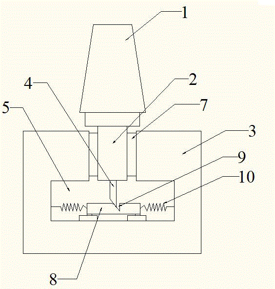
[0015] like figure 1 The yarn-releasing roller mechanism shown includes: a yarn-releasing roller, a base 3 and a pin 4 . The yarn releasing roller is divided into: a roller shaft 2 and a roller 1, and the roller 1 is sleeved on the roller shaft 2. Latch 4 is fixed on roller shaft 2 bottoms. The base 3 is arranged on the bottom end of the roller shaft 2, the base 3 is formed with a mounting hole and a placement cavity 5 arranged below the mounting hole, a bearing 7 is arranged in the mounting hole, and the bottom end of the roller shaft 2 passes through the bearing 7 and the base 3 Constitute the vertical rotation connection of the rotation axis and the sliding connection in the vertical direction. The placement chamber 5 is provided with a slider 8 and an elastic assembly. The slider 8 and the base 3 form a horizontal sliding connection...


PUM


Abstract

The invention discloses a yarn releasing roll mechanism, which comprises a yarn releasing roll, wherein the yarn releasing roll is divided into a roll shaft and a roller which is sleeved on the roll shaft, and the yarn releasing roll mechanism also comprises a substrate which is arranged on the bottom end of the roll shaft and a plugging pin which is fixed on the bottom end of the roll shaft; the substrate is provided with an installation hole and a placement cavity which is arranged below the installation hole, a bearing is arranged inside the installation hole, the bottom end of the roll shaft is connected with the substrate through the bearing in a rotation way that the rotation axis is vertical and connected with the substrate through the bearing in a sliding way in the vertical direction, a slide block and an elastic assembly are arranged inside the placement cavity, the slide block is connected with the substrate in a sliding way in the horizontal direction, and the elastic assembly is arranged between the wall of the placement cavity and the slide block; and the bottom end of the plugging pin forms an oblique plug, and the top surface of the slide block is provided with an oblique groove which is used for the oblique plug to plug in. The yarn releasing roll mechanism has the beneficial effects that the weight of yarns on the yarn releasing roll can be known, the rotation of the yarn releasing roll can be automatically controlled to start and stop, and the yarn releasing quantity can be precisely controlled.

Description

technical field [0001] The invention relates to mechanical parts in weaving, in particular to a yarn releasing roller mechanism. Background technique [0002] With the development of the economy, people's demand for textile products is increasing. The improvement of the equipment used for textile has greatly promoted the efficiency of textile production. In textile production, yarn unwinding from bobbins is an essential production link. In previous yarn unwinding equipment, the mode of free yarn unwinding was often adopted. [0003] However, with the development of science and technology, in some precision equipment with higher requirements, it is hoped that the amount of yarn unwinding can be accurately controlled. Now servo motors are often used for control, but there is no one that can accurately respond to the yarn on the yarn roller. weight device. Contents of the invention [0004] In order to solve the deficiencies of the prior art, the object of the present inve...

Claims


Application Information

Patent Timeline
Patent Type & Authority Applications(China)
IPC IPC(8): B65H49/18
Inventor 高飞
Owner WUJIANG DONGFEI CHEM FIBER
Why Eureka
Try Eureka