Bridge expansion joint with variable-rigidity clamping end

A clamping end and expansion joint technology, applied in the field of expansion joints, can solve problems such as troublesome replacement, difficult maintenance and replacement, weak clamping and failure of the clamping end, etc., and achieves the effect of high strength and modulus

Active Publication Date: 2013-03-20
RAILWAY ENG RES INST CHINA ACADEMY OF RAILWAY SCI
View PDF16 Cites 2 Cited by
  • Summary
  • Abstract
  • Description
  • Claims
  • Application Information

AI Technical Summary

Problems solved by technology

Its structure is relatively complicated, and it is troublesome to replace
[0006] Therefore, it is necessary to design a new type of expansion joint with high reliability

Method used


Image

  • Bridge expansion joint with variable-rigidity clamping end
  • Bridge expansion joint with variable-rigidity clamping end

Examples


Example Embodiment

[0015] Example 1

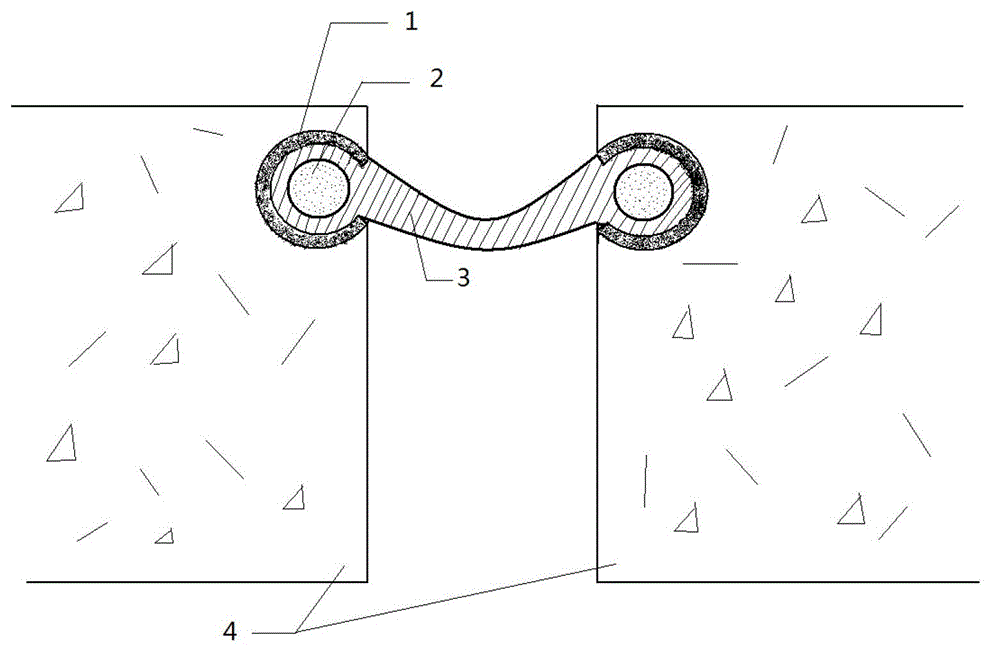
[0016] see figure 1 , which shows a bridge expansion joint with a variable stiffness clamping end according to a preferred embodiment of the present invention, the expansion joint includes a body 3, a variable stiffness clamping end and a fixed edge beam 1, the body 3 and a variable stiffness clamping end Connected into one body, the fixed side beam 1 is embedded in the bridge beam end 4 and forms a receiving groove, the clamping end is embedded in the receiving groove, and the clamping end includes a cavity 2 and a connection with the cavity 2 A sealable opening (not shown in the figures) is used for filling the cavity 2 with a hardenable filling material in a fluid state.

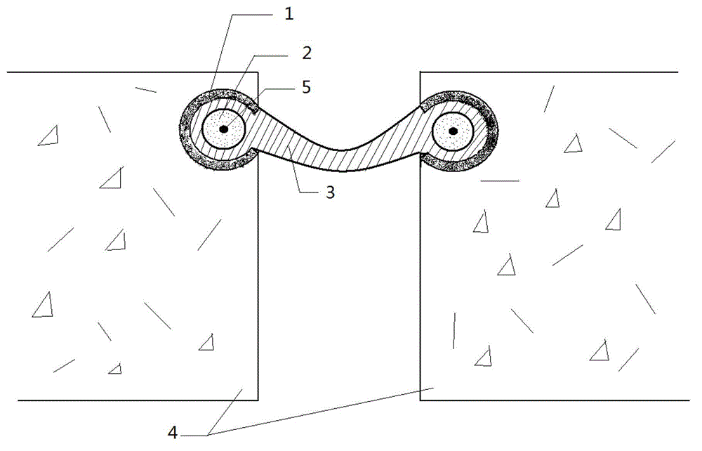
[0017] Preferably, the filling material is resin. Preferably, the resin is gas, liquid or solid powder. Preferably, see figure 2 , the cavity 2 is provided with a heating wire 5, it can be understood that the filling material can also use other ways to change the stiffness. Prefer...

Example Embodiment

[0019] Example 2

[0020] The expansion joint includes a rubber strip body 3 , a clamping end with variable stiffness, a fixed side beam 1 and an anchoring device (not shown in the figure). Wherein the anchoring device is used for anchoring and fixing the side beam 1 .

[0021] as attached figure 2 , the fixed side beam 1 adopts a metal side beam. The expansion joint body 3 adopts a rubber waterstop. The clamping end is a cavity structure, and the heating wire 5 is placed in it in advance. The cavity at the clamping end is filled with variable stiffness material. The variable stiffness material can be resin.

[0022] Installation process

[0023] Before installation, anchor and fix the side beam 1. The heating wire 5 is put into the cavity 2 at the clamping end of the expansion joint. Flatten the clamping end of the expansion joint and embed it in the receiving groove of the side beam 1. Use a plunger pump to inject resin into the cavity 2 at the clamping end of the ...


PUM

PropertyMeasurementUnit
Hardnessaaaaaaaaaa

Abstract

The invention discloses a bridge expansion joint with a variable-rigidity clamping end, which comprises a main body, the clamping end and a fixed boundary beam, wherein the rigidity of the clamping end is variable; when being mounted, the rigidity of the clamping end is lower, so that the clamping end is conveniently inserted into a groove of the fixed boundary beam. When being used, the rigidity of the clamping end is enlarged, and the clamping force is greatly improved to prevent falling off of the expansion joint and greatly improve the working reliability. When being changed and disassembled, the rigidity of the clamping end is greatly reduced, so that the clamping end can be separated from the groove of the fixed boundary beam easily. Therefore, the bridge expansion joint can be easily constructed and replaced.

Description

technical field [0001] The invention relates to an expansion joint between bridges, which is suitable for a dynamic joint between structures and simultaneously plays the roles of waterproof, dustproof and sealing. Specifically, a bridge expansion joint with clamping ends of variable stiffness, featuring high reliability and easy replacement. Background technique [0002] At present, the expansion joints widely used in my country's railway bridges are rubber waterstop structures. This type of expansion joints mainly includes three parts: fixed side beams, waterproof rubber strips and anchoring devices. The survey found that the rubber waterstop expansion joints used in many railways in operation have problems such as peeling and falling off to varying degrees, resulting in the complete failure of the waterproof and drainage performance of the expansion joints. Engineering practice shows that the waterstop expansion joints have embedded The structure and installation process ...

Claims


Application Information

Patent Timeline
IPC IPC(8): E01D19/06
Inventor 牛斌胡所亭王乐然唐功庆郭晨
Owner RAILWAY ENG RES INST CHINA ACADEMY OF RAILWAY SCI
Why Eureka
Try Eureka