Electronic detonator network detector and detection method
A network detector and electronic detonator technology, applied in weapon accessories, fuzes, offensive equipment, etc., can solve problems such as failure to detect line leakage, insufficient detonator energy, unsafe hidden dangers, etc., to facilitate network troubleshooting and improve blasting effect. effect of effect
- Summary
- Abstract
- Description
- Claims
- Application Information
AI Technical Summary
Problems solved by technology
Method used
Image
Examples
Embodiment 2
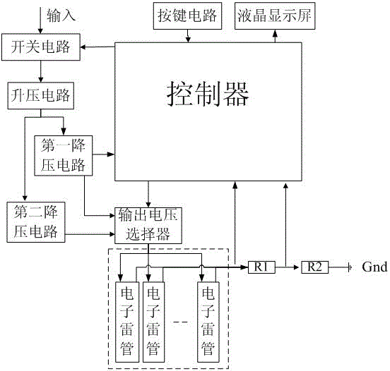
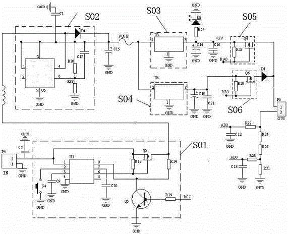
[0080] Embodiment two: if figure 2 As shown, on the basis of Embodiment 1, the power supply unit includes a switch circuit S01, a boost circuit S02, a first step-down circuit S03, and a second step-down circuit S04, and the input port of the switch circuit S01 is connected to the input voltage signal , the output port of the switch circuit S01 is respectively connected to the input port of the processor and the boost circuit S02, and the first output port and the second output port of the boost circuit S02 are respectively connected to the first step-down circuit S03 and the second step-down circuit S04 , the first step-down circuit S03 and the second step-down circuit S04 are respectively connected to two input ports of the output voltage selector.
Embodiment 3
[0081] Embodiment 3: On the basis of Embodiment 1 or 2, the output voltage selector includes a first voltage circuit S05 and a second voltage circuit S06, and the first circuit includes an eighteenth resistor R18 and a fourth MOS transistor Q4. The source of the fourth MOS transistor Q4 is connected to the output terminal of the first step-down circuit S03, the eighteenth resistor R18 is connected between the gate of the fourth MOS transistor Q4 and the source of the fourth MOS transistor Q4, and the fourth The collector of the MOS transistor Q4 is the output end of the first voltage circuit S05, the gate of the fourth MOS transistor Q4 is connected to the processor, and the output end of the first voltage circuit S05 outputs a large voltage signal U. The second voltage circuit S06 includes a twentieth resistor R20 and a sixth MOS transistor Q6, the source of the sixth MOS transistor Q6 is connected to the output terminal of the second step-down circuit S04, and the twentieth r...
Embodiment 4
[0082] Embodiment 4: On the basis of one of Embodiments 1 to 3, the specific process of data processing by the processor is:
[0083] Step 1: The processor obtains the sampling voltage drop value U12 through the sampling circuit, and the sum of the sampling voltage drop value U12 and the electronic detonator network voltage drop value U11 is the output voltage selector output large voltage value U, and the sampling is obtained by formula (1) Current I2:
[0084] I2=U12 / R f (1)
[0085] where R f is the resistance value of the sampling resistor R1;
[0086] Step 2: Obtain the voltage drop value U11 of the electronic detonator network by formula (2):
[0087] U11=U-U12 (2)
[0088] Check the current and voltmeter through the voltage drop value U11 of the electronic detonator network, and obtain the network current value I1 corresponding to the single detonator at the voltage drop value U11 of the electronic detonator network;
...
PUM
 Abstract
Description
Claims
Application Information
 - R&D
- Intellectual Property
- Life Sciences
- Materials
- Tech Scout
- Unparalleled Data Quality
- Higher Quality Content
- 60% Fewer Hallucinations
Browse by: Latest US Patents, China's latest patents, Technical Efficacy Thesaurus, Application Domain, Technology Topic, Popular Technical Reports.
© 2025 PatSnap. All rights reserved.Legal|Privacy policy|Modern Slavery Act Transparency Statement|Sitemap|About US| Contact US: help@patsnap.com


