Supercharge Your Innovation With Domain-Expert AI Agents!

Three-phase current detection circuit for frequency converter

A three-phase current and detection circuit technology, applied in the field of frequency converters, can solve the problems of low current detection accuracy, increased cost, and high cost

Active Publication Date: 2014-12-10
SHENZHEN AMBITION ELECTRONICS
View PDF4 Cites 0 Cited by
  • Summary
  • Abstract
  • Description
  • Claims
  • Application Information

AI Technical Summary

Problems solved by technology

In the existing inverter products, Hall elements are usually used together with some peripheral circuits to detect current. Although this technical means is relatively mature and commonly used, its high price adds a lot of cost to the inverter. In particular, it has caused a great cost burden for the mass production of enterprises, making many inverter companies discouraged.
In order to replace the Hall element, some engineers short-circuit the three branches of the lower bridge arm of the inverter unit, and then ground through a milliohm resistor, and then further detect the current on the milliohm resistor. Although this detection method is simple , but because the three branches of the lower bridge arm have been short-circuited, and the current reflected on the milliohm resistance is not the real current of each branch, so when this method is used for current detection, the accuracy is very low
Therefore, the existing three-phase current detection circuit used for frequency converter has high cost and low accuracy of current detection

Method used


Image

  • Three-phase current detection circuit for frequency converter
  • Three-phase current detection circuit for frequency converter
  • Three-phase current detection circuit for frequency converter

Examples


Embodiment Construction

[0018] The present invention will be described in more detail below in conjunction with the accompanying drawings and embodiments.

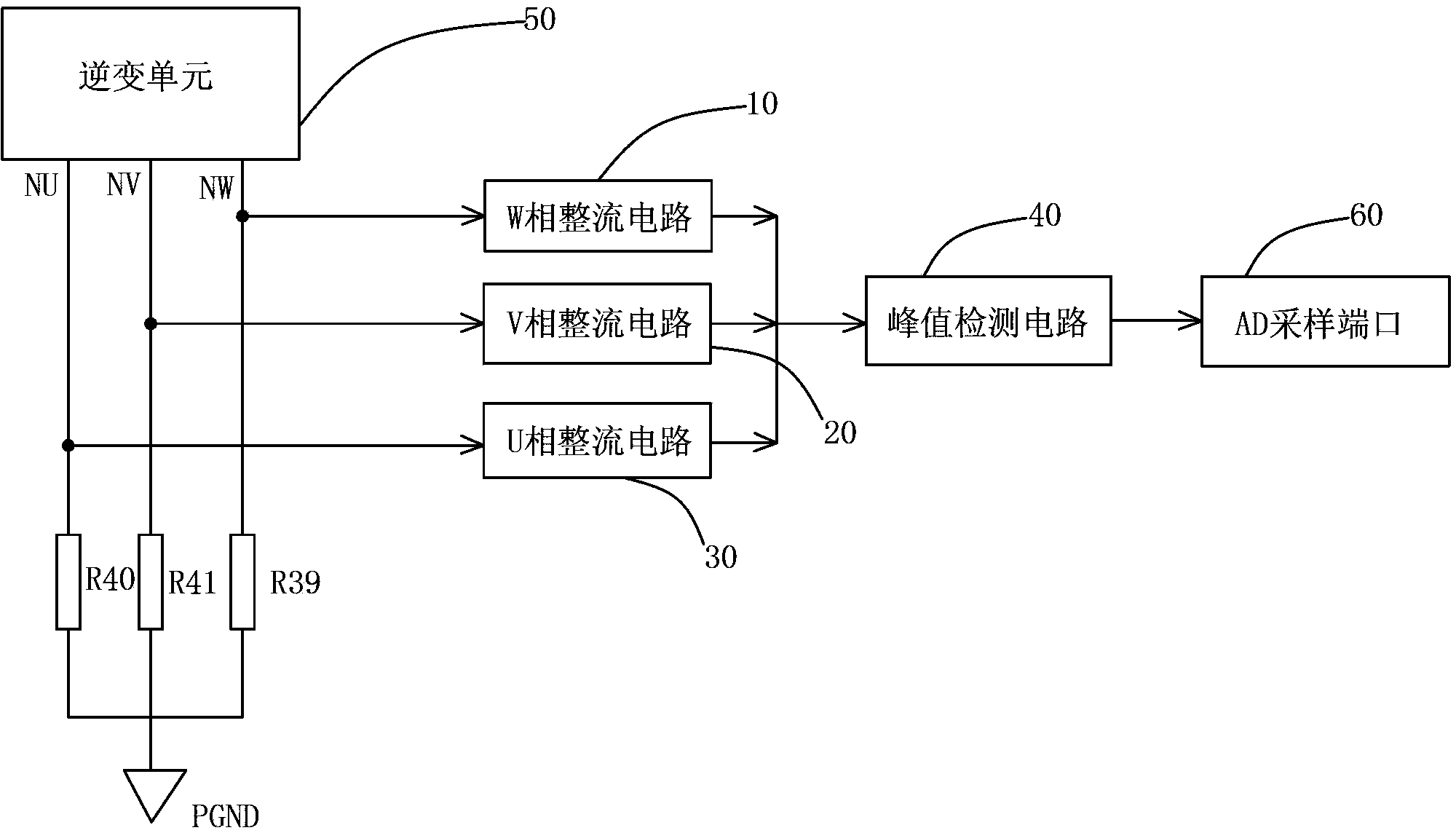
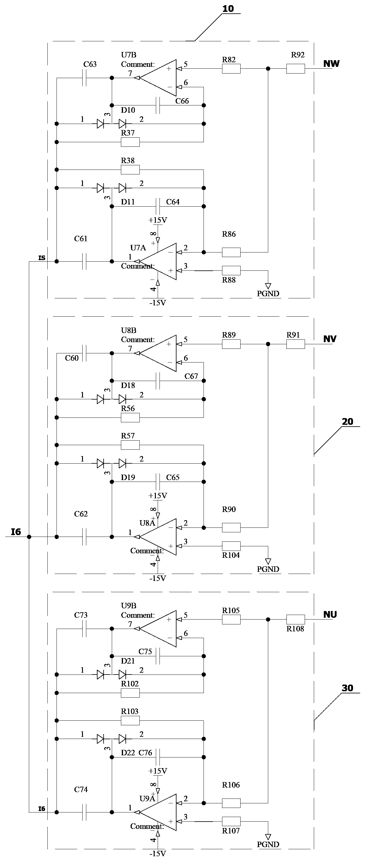
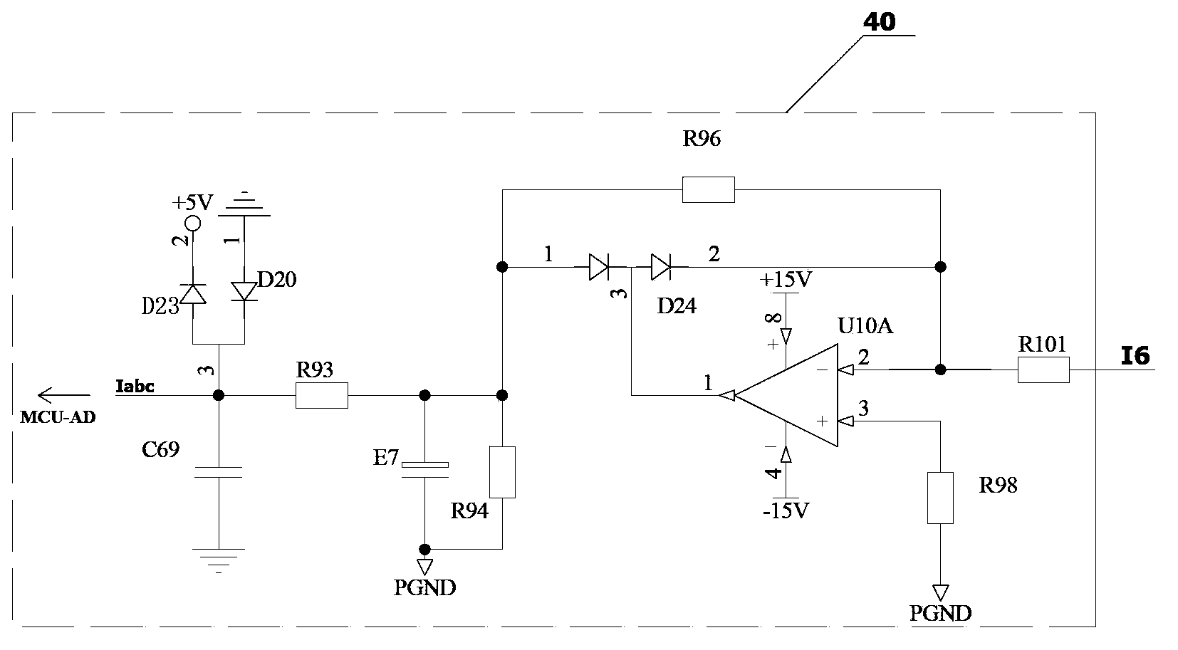
[0019] The invention discloses a three-phase current detection circuit for a frequency converter, which combines figure 1 with Figure 5 As shown, it includes a W-phase rectifier circuit 10, a V-phase rectifier circuit 20, a U-phase rectifier circuit 30, and a peak detection circuit 40. The three-phase current detection circuit also includes a milliohm resistor R39, a milliohm resistor R39, and a milliohm resistor R39. The resistor R41 and a milliohm resistor R40 are respectively connected between the three lower bridge arms of the inverter unit 50 and the ground, the milliohm resistor R39, the milliohm resistor R41 and the milliohm resistor R40 are current sampling resistors, and The voltages generated by the three are respectively rectified and processed by the W-phase rectifier circuit 10, the V-phase rectifier circuit 20, and the U-phase rec...


PUM


Abstract

The invention discloses a three-phase current detection circuit for a frequency converter. The three-phase current detection circuit comprises a W-phase rectification circuit, a V-phase rectification circuit, a U-phase rectification circuit, a peak value detection circuit, and a milliohm resistor R39, a milliohm resistor R41 and a milliohm resistor R40 which are respectively connected between three lower bridges arms of an inversion unit and the ground, wherein the milliohm resistor R39, the milliohm resistor R41 and the milliohm resistor R40 are current sampling resistors; voltage produced by the milliohm resistor R39, the milliohm resistor R41 and the milliohm resistor R40 is output to the peak value detection circuit after being rectified by the W-phase rectification circuit, the V-phase rectification circuit and the U-phase rectification circuit; and then a peak value voltage signal is obtained by the peak value detection circuit and transmitted to an analog digital (AD) sampling port of a single chip microcomputer. Compared with the prior art, the three-phase current detection circuit has the advantages that not only can the overall cost of the frequency converter be reduced, but also the current detection accuracy of the frequency converter can be improved.

Description

technical field [0001] The invention relates to the technical field of frequency converters, in particular to a three-phase current detection circuit for frequency converters. Background technique [0002] Inverter is one of the indispensable and important devices in modern motor speed control and energy-saving products. It is widely used in the industrial field. With the advancement of science and technology, inverter technology has also developed rapidly. In order to ensure the safe and stable operation of the asynchronous motor, it is usually necessary to detect the current in the inverter circuit and feed the current back to the single-chip microcomputer to realize real-time monitoring of the current. In the existing inverter products, Hall elements are usually used together with some peripheral circuits to detect current. Although this technical means is relatively mature and commonly used, its high price adds a lot of cost to the inverter. In particular, it has caused...

Claims


Application Information

Patent Timeline
Patent Type & Authority Patents(China)
IPC IPC(8): G01R19/25
Inventor 邢起义
Owner SHENZHEN AMBITION ELECTRONICS
Features
  • R&D
  • Intellectual Property
  • Life Sciences
  • Materials
  • Tech Scout
  • Unparalleled Data Quality
  • Higher Quality Content
  • 60% Fewer Hallucinations
Learn More