Resistor calibration circuit

A technology of calibrating circuit and current calibration, applied in the directions of amplifying control device circuits, electrical components, adjusting electrical variables, etc., can solve the problems of low efficiency and low adjustment accuracy, and achieve the effect of ensuring accuracy and improving adjustment efficiency.

Active Publication Date: 2013-03-20
IPGOAL MICROELECTRONICS (SICHUAN) CO LTD
View PDF8 Cites 4 Cited by
  • Summary
  • Abstract
  • Description
  • Claims
  • Application Information

AI Technical Summary

Problems solved by technology

However, this method has low efficiency and low adjustment accuracy, and it is difficult to adjust the resistance values ​​of all the resistors in the chip to the desired value with higher accuracy.

Method used


Image

  • Resistor calibration circuit
  • Resistor calibration circuit
  • Resistor calibration circuit

Examples


Embodiment Construction

[0018] Embodiments of the present invention will now be described with reference to the drawings, in which like reference numerals represent like elements. As mentioned above, the present invention provides a resistance calibration circuit, which can automatically adjust the resistance value of the voltage-controlled resistor to be calibrated, and has high adjustment accuracy and high efficiency.

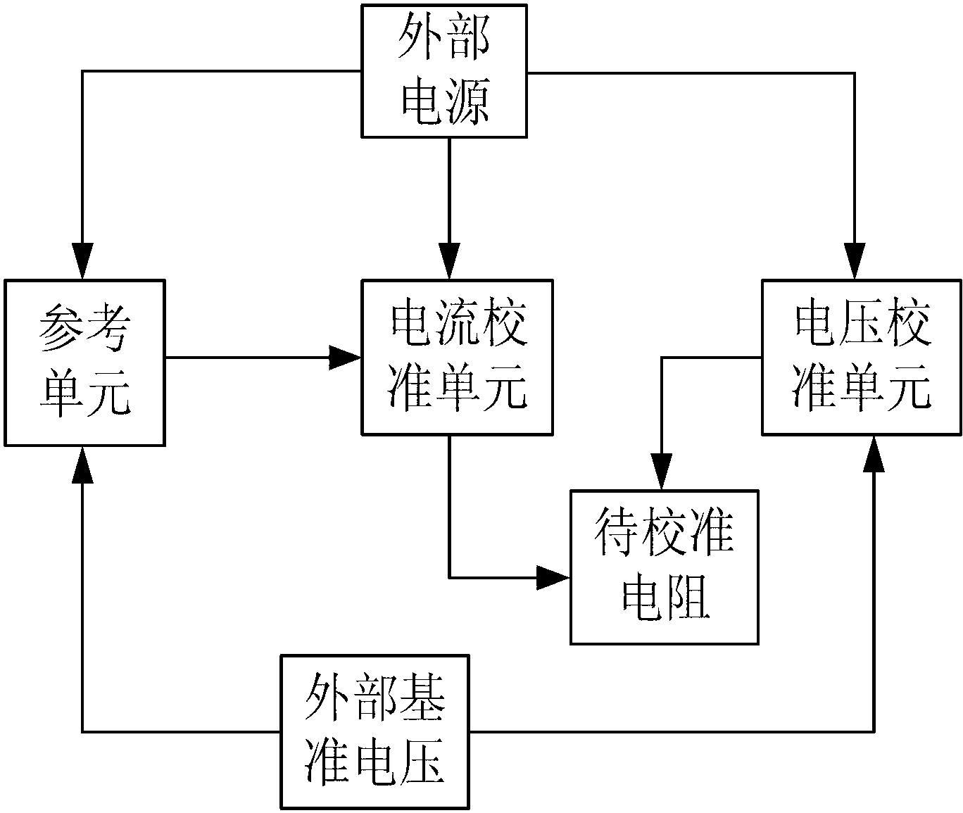
[0019] Please refer to figure 1 , figure 1 It is a structural block diagram of the resistance calibration circuit of the present invention. As shown in the figure, the resistance calibration circuit of the present invention includes an external power supply, a reference unit, a current calibration unit, and a voltage calibration unit respectively connected to the external power supply, and an external reference voltage connected to the reference unit and the voltage calibration unit respectively, respectively. The voltage-controlled resistance to be calibrated connected to the cur...


PUM


Abstract

The invention discloses a resistor calibration circuit which comprises an external power supply, a reference unit, a current calibration unit, a voltage calibration unit, external reference voltage, a voltage-controlled resistor to-be-calibrated, wherein the reference unit, the current calibration unit and the voltage calibration unit are respectively connected with the external power supply, external reference voltage is respectively connected with the reference unit and the voltage calibration unit, the voltage-controlled resistor to-be-calibrated is respectively connected with the current calibration unit and the voltage calibration unit, and the current calibration unit is further connected with the reference unit. The resistor calibration circuit can automatically adjust a resistance value of the voltage-controlled resistor to-be-calibrated, and is high in adjusting accuracy and efficiency.

Description

technical field [0001] The invention relates to the field of integrated circuits, and more particularly relates to a resistance calibration circuit which can automatically calibrate the resistance value of an internal resistance in a chip. Background technique [0002] In the manufacturing process of various chips, since the resistance value of the on-chip resistor varies greatly with the process, it is usually difficult to directly manufacture the on-chip resistor with accurate resistance value, so the resistance value of the on-chip resistor needs to be calibrated additionally. [0003] In the prior art, the resistance value of the on-chip resistor is usually calibrated manually, that is, the resistance value of the resistor in the chip is tested and the resistance value is controlled and adjusted accordingly to obtain a more accurate resistance value. However, this method has low efficiency and low adjustment accuracy, and it is difficult to adjust the resistance values ​...

Claims


Application Information

Patent Timeline
Patent Type & Authority Applications(China)
IPC IPC(8): G05F1/56
CPCH03G1/007H03G1/0029
Inventor 范方平
Owner IPGOAL MICROELECTRONICS (SICHUAN) CO LTD
Why Eureka
Try Eureka