Supercharge Your Innovation With Domain-Expert AI Agents!

Motor stator with deformable iron core and manufacturing method thereof

A motor stator and iron core technology, which is applied in the field of motor stator preparation, can solve the problems of reduced motor efficiency, low full rate of wire slots, low production efficiency, etc., and achieves the effect of ensuring the full rate of slots

Active Publication Date: 2013-03-20
珠海市瑞美电机有限公司
View PDF5 Cites 4 Cited by
  • Summary
  • Abstract
  • Description
  • Claims
  • Application Information

AI Technical Summary

Problems solved by technology

However, the price of a special winding equipment is more than 1.3 million yuan, which makes the equipment investment large; the production efficiency of this machine is low, and it can produce 20 stators per hour, so the process time is long, the production efficiency is low, and the process cost is high.
Secondly, because the gap between the slots and the winding tool must be reserved so that the winding process can be carried out, the number of coil windings in the slots is not many, resulting in a low slot fill rate of the slots.
Furthermore, due to the requirements of the winding process, a certain width of the notch of the wire slot must be maintained, but a wider notch width will increase the vibration of the motor and reduce the efficiency of the motor

Method used


Image

  • Motor stator with deformable iron core and manufacturing method thereof
  • Motor stator with deformable iron core and manufacturing method thereof
  • Motor stator with deformable iron core and manufacturing method thereof

Examples


Embodiment Construction

[0034] A specific embodiment of a motor stator provided with a deformable iron core of the present invention will now be described with reference to the accompanying drawings.

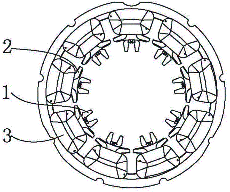
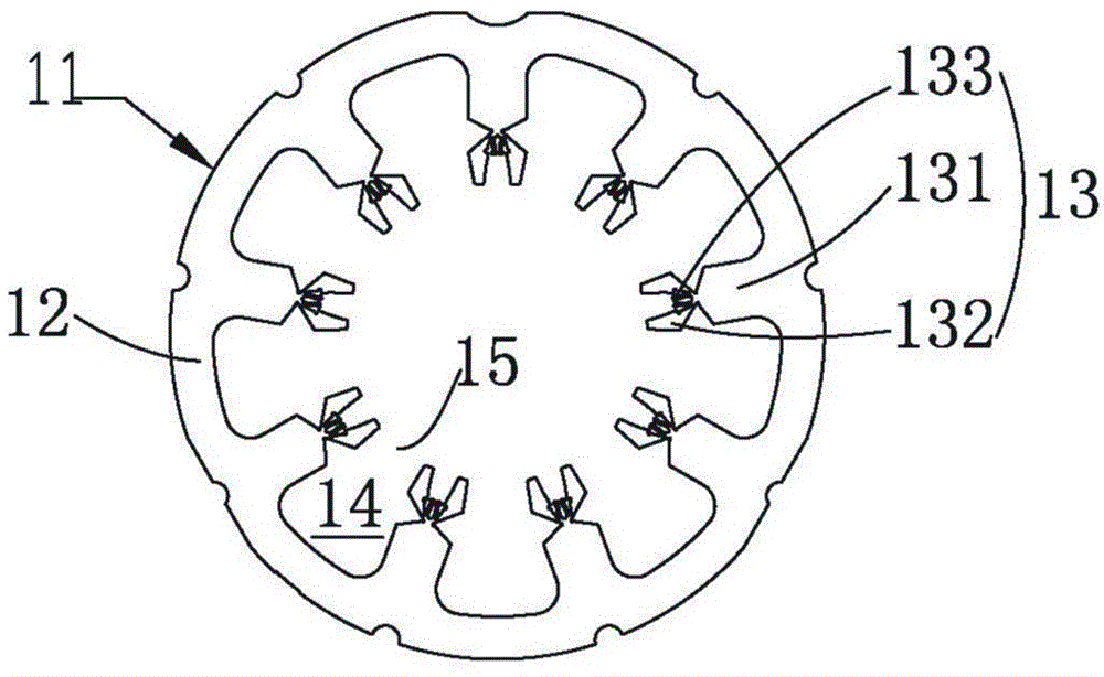
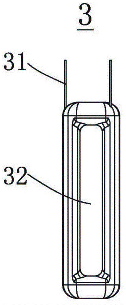
[0035] see Figure 1 to Figure 4 As shown, Embodiment 1 of the present invention, a motor stator provided with a deformable core of the present invention includes a stator core 1, a coil 3 and an insulating component 2, and the stator core 1 is formed by stacking a plurality of one-piece stator chips 11 The stator core 11 is made of magnetically conductive material, the stator core 11 includes a magnetically conductive ring 12, a Y-shaped magnetic pole 13 that protrudes inward along the inner side of the magnetically conductive ring 12 and is uniformly distributed in the axial direction, and two magnetic poles of the Y-shaped magnetic pole 13 The wings 132 can be expanded to both sides, and a wire groove 14 is formed between two adjacent magnetic poles 13 and the inner surface of the magnetic conductio...


PUM


Abstract

The invention discloses a motor stator with a deformable iron core. The motor stator with the deformable iron core comprises an iron core of a stator, coils and an insulation component, wherein the iron core of the stator is formed by stacking of a plurality of one-piece type chips. The motor chip comprises a magnetic ring, and Y-shaped magnetic poles protruding along the inner side face of magnetic ring and arranged evenly along an axial direction. Two magnetic pole wings of the Y-shaped magnetic poles can be expanded to two sides, wire casings are formed between two adjacent magnetic poles and by the inner side face of the magnetic ring, notches are formed at edges of two opposite magnetic pole wings of the magnetic pole, and widths of the notches are correspondingly changed with expansion of the magnetic pole wings. The coils are sleeved at the trunk of the Y-shaped magnetic poles and are arranged at wire housings at two sides of the trunk. The insulation component is arranged between the iron core and the coils and enables the stator iron core to be insulated with the coils. The invention further provides a manufacturing method of the motor stator with a deformable iron core. Due to the deformable magnetic pole, the manufacturing method of the motor stator with the deformable iron core enables the notches to be small, does not need to wind coils directly on the stator iron core to improve craft efficiency, and slot fill factors of the wire housings are high.

Description

technical field [0001] The invention relates to a motor stator, in particular to a motor stator provided with a deformable iron core. The invention also relates to a method for preparing a motor stator provided with a deformable iron core. Background technique [0002] The magnetic pole of the stator iron core of the existing motor is fixed T-shaped, and the coil is directly wound on the stator iron core by a special winding device. However, the price of a special winding equipment is more than 1.3 million yuan, which makes the equipment investment large; the production efficiency of this machine is low, and it can produce 20 stators per hour, so the process time is long, the production efficiency is low, and the process cost is high. Secondly, since the gap between the slots and the winding tool must be reserved so that the winding process can be carried out, the number of coil windings in the wire slots is not many, resulting in a low slot fill rate of the wire slots. Fu...

Claims


Application Information

Patent Timeline
IPC IPC(8): H02K1/16H02K3/34H02K15/02
Inventor 杜小兵
Owner 珠海市瑞美电机有限公司
Features
  • R&D
  • Intellectual Property
  • Life Sciences
  • Materials
  • Tech Scout
  • Unparalleled Data Quality
  • Higher Quality Content
  • 60% Fewer Hallucinations
Learn More