Dimming lamp

A dimming lamp and dimming driving technology, applied in the direction of light source, electric light source, electric lamp circuit layout, etc., can solve the problems of reducing the service life of lamps, cumbersome, uncomfortable for human eyes, etc. simple effect

Inactive Publication Date: 2013-03-20
GUANGDONG MEIYAN HYDROPOWER CO LTD
View PDF4 Cites 6 Cited by
  • Summary
  • Abstract
  • Description
  • Claims
  • Application Information

AI Technical Summary

Problems solved by technology

Since the brightness is changed by calculating the number of ON / OFF switching of the switch, it can only adjust the brightness of the light discretely. The brightness of the light will be divided into several levels, and each different level of brightness corresponds to a different number of ON / OFF switch switching. , it cannot linearly adjust the brightness of the light at will
At the same time, when adjusting the brightness of the lamp, it is necessary to switch the switch ON / OFF frequently, resulting in the frequent on and off of the LED lamp, which is not only cumbersome, but also makes the human eyes uncomfortable, and most importantly, it will reduce the service life of the lamp.

Method used


Image

  • Dimming lamp
  • Dimming lamp
  • Dimming lamp

Examples


Embodiment 1

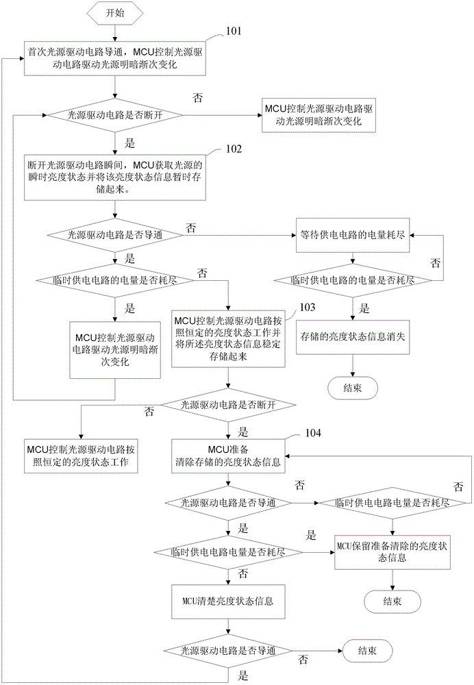
[0070] like figure 1 As shown, this embodiment provides a dimming driving method, which is based on sending a signal to control the brightness of the light source through the MCU to the light source driving circuit to control the brightness of the light source. Specifically, the method includes:

[0071] 101. The light source driving circuit is turned on for the first time, and the MCU controls the light source driving circuit to drive the light source to change gradually. Specifically: solidify a program in the MCU, the program corresponds to the control signal that drives the light source from bright to dark, and then gradually from dark to bright, and turns on the switch that controls the light source drive circuit for the first time. The light source driving circuit is turned on, and the light source driving circuit provides power for the MCU and the light source. After the light source driving circuit is turned on, the MCU starts to work, and the light source is also lit...

Embodiment 2

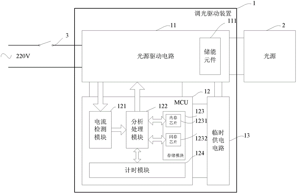
[0080] like image 3 As shown, this embodiment provides a dimming lamp, the dimming lamp includes a dimming driving device 1 and a light source 2 connected to the dimming driving device, the dimming driving device is controlled by a switch 3, the dimming The driving device 1 includes a light source driving circuit 11, an MCU 12 and a temporary power supply circuit 13, the light source driving circuit 11 is used to supply power to the MCU 12 and the light source 2, and the temporary power supply circuit 13 is used to continue To supply power to the MCU 12 , the light source driving circuit 11 is also used to charge the temporary power supply circuit 13 . The light source drive circuit 11 also includes an energy storage element 111 for continuing to supply power to the light source 2 after the switch 3 connected to the light source drive circuit 11 is disconnected, and the MCU 12 includes a current detection module 121, an analysis processing module 122 and a storage module 123...

Embodiment 4

[0088] In the above-mentioned embodiment 3, a timing module 124 is set in the MCU. The timing module 124 obtains the time when the light source driving circuit 11 is turned on to off when the light source 2 is in a state of gradually changing light and dark and the light source driving circuit 11 is turned off; The analysis and processing module 122 searches for the constant brightness state of the light source corresponding to the time in a preset program and temporarily stores the constant brightness state information. The difference from the above-mentioned embodiment 3 is that a signal sampling module 125 is set in the MCU, and the signal sampling module 125 is used for: when the light source 2 is in the state of gradually changing brightness and darkness and the light source driving circuit 11 is turned off, the light source 2 is working. The current or / and voltage value is sent to the analysis processing module 122 , and the analysis processing module 122 stores the curre...


PUM


Abstract

The invention relates to dimming driving device and a dimming lamp with the dimming driving device. The dimming driving device comprises a light source drive circuit and is characterized by further comprising a Microprogrammed Control Unit (MCU) and a temporary power supply circuit, wherein the temporary power supply circuit is used for supplying electricity to the MCU after the light source drive circuit stops supplying electricity. The MCU comprises a current detection module, an analysis processing module and a storage module, wherein the current detection module is used for obtaining breakover/cutoff signals of the light source drive circuit and transmitting to the analysis processing module. The storage module is used for storing a curing program for gradual light source brightness and darkness change and status information about light source brightness constancy. The analysis processing module obtains the breakover/cutoff signals of the light source drive circuit, analyzes and processes the curing program for the gradual light source brightness and darkness change or the status information about light source brightness constancy, wherein the curing program for the gradual light source brightness and darkness change or the status information about light source brightness constancy are stored by the storage module, to generate light source brightness regulating signals, and transmits the light source brightness regulating signal to the light source drive circuit. And the light source drive circuit regulates the brightness of the light source according to control signals.

Description

[0001] This application is a divisional application of the following patents [0002] Application number: 201010179404.3 [0003] Application date: May 21, 2010 [0004] Name of invention: a dimming driving method, device and dimming lamp technical field [0005] The invention belongs to the technical field of illuminating lamp control, and relates to a dimming driving method and device and a dimming lamp with the dimming driving device. The dimming driving device controls and adjusts the brightness of a light source together with an on-off switch. Background technique [0006] In the case of increasingly tense energy sources, energy saving of lighting fixtures has become an increasingly important topic. At present, the direction of energy saving of lighting fixtures is mainly to replace traditional incandescent lamps with energy-saving lamps such as fluorescent lamps or LEDs, but there are few directions for dimming. With the development of technology, by timely adjusting...

Claims


Application Information

Patent Timeline
Patent Type & Authority Applications(China)
IPC IPC(8): H05B37/02
Inventor 冯林
Owner GUANGDONG MEIYAN HYDROPOWER CO LTD
Why Eureka
Try Eureka