
Shot treatment device

A technology of shot peening treatment and tools, which is applied in the field of shot peening treatment devices, can solve the problems such as the decrease of projection efficiency, and achieve the effect of improving projection efficiency

Active Publication Date: 2013-03-20
SINTOKOGIO LTD
View PDF9 Cites 3 Cited by
  • Summary
  • Abstract
  • Description
  • Claims
  • Application Information

AI Technical Summary

Problems solved by technology

[0004] However, in the shot blasting device described in Patent Document 1, when projecting projected materials from each centrifugal projection machine, there are projected materials from the centrifugal projected machine equipped on the upper part of the shot blasting chamber and the projected material from the centrifugal projecting machine equipped in the shot blasting chamber. There is concern that the projection materials in the lower part of the centrifugal projection machine will cancel each other out and the projection efficiency will decrease.

Method used


Image

  • Shot treatment device
  • Shot treatment device
  • Shot treatment device

Examples


Embodiment Construction

[0027] First, a first embodiment of the present invention will be described.

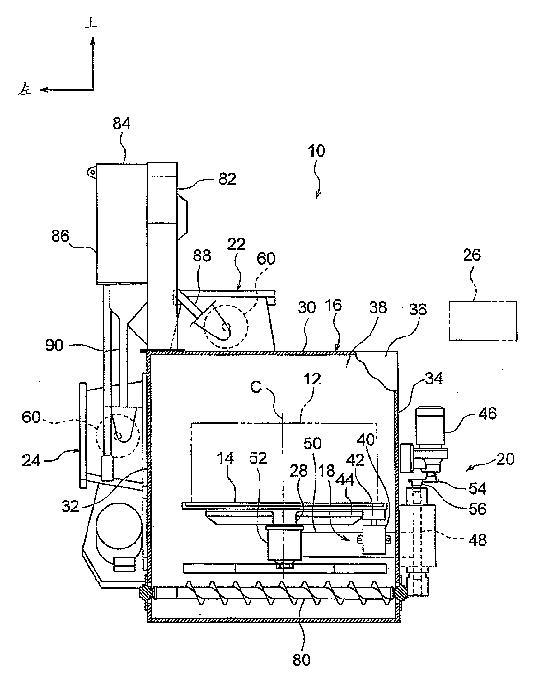
[0028] In addition, the arrow front, upper side, and left shown in each figure represent the front side, upper side, and left side of the shot processing apparatus 10 demonstrated below.

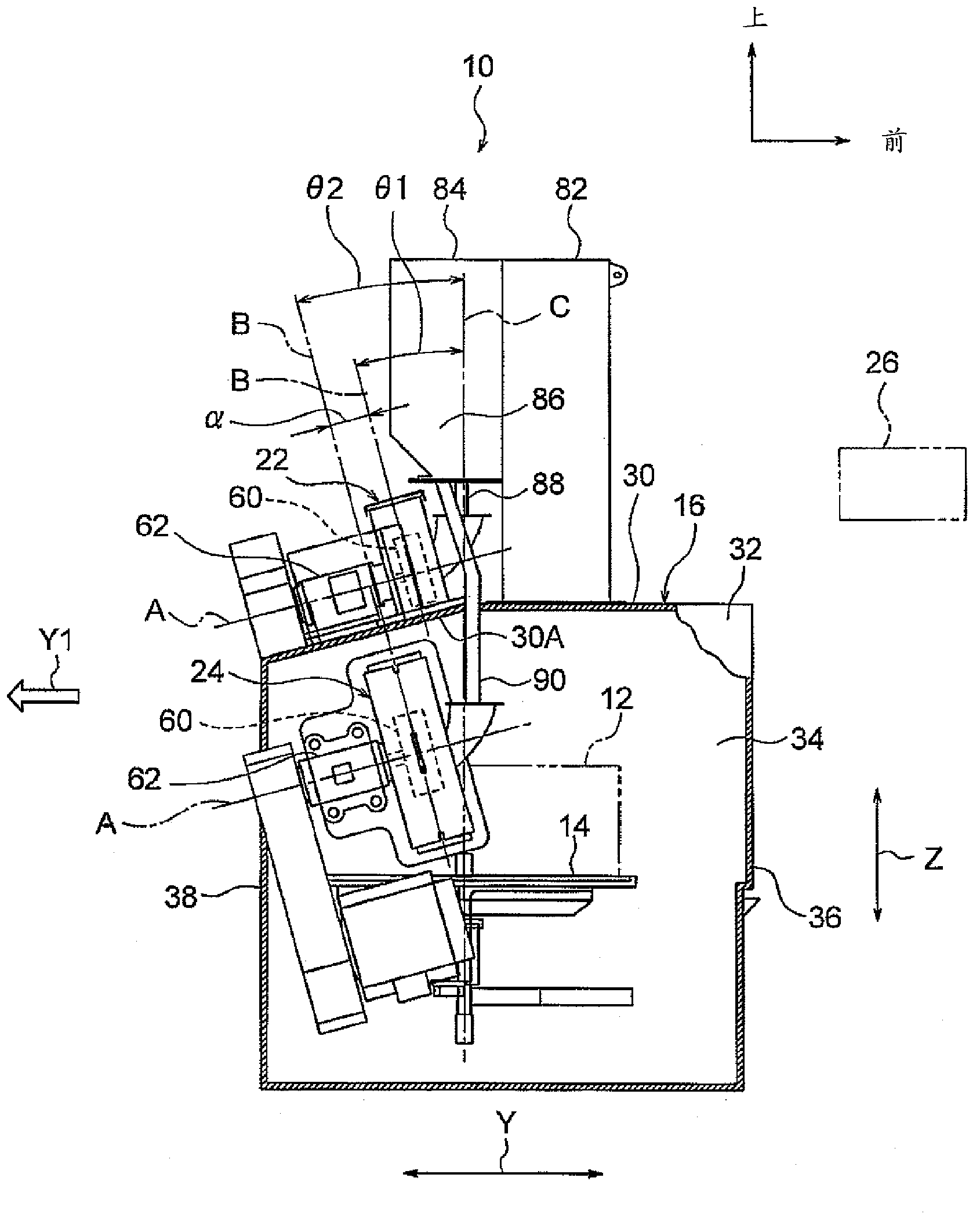
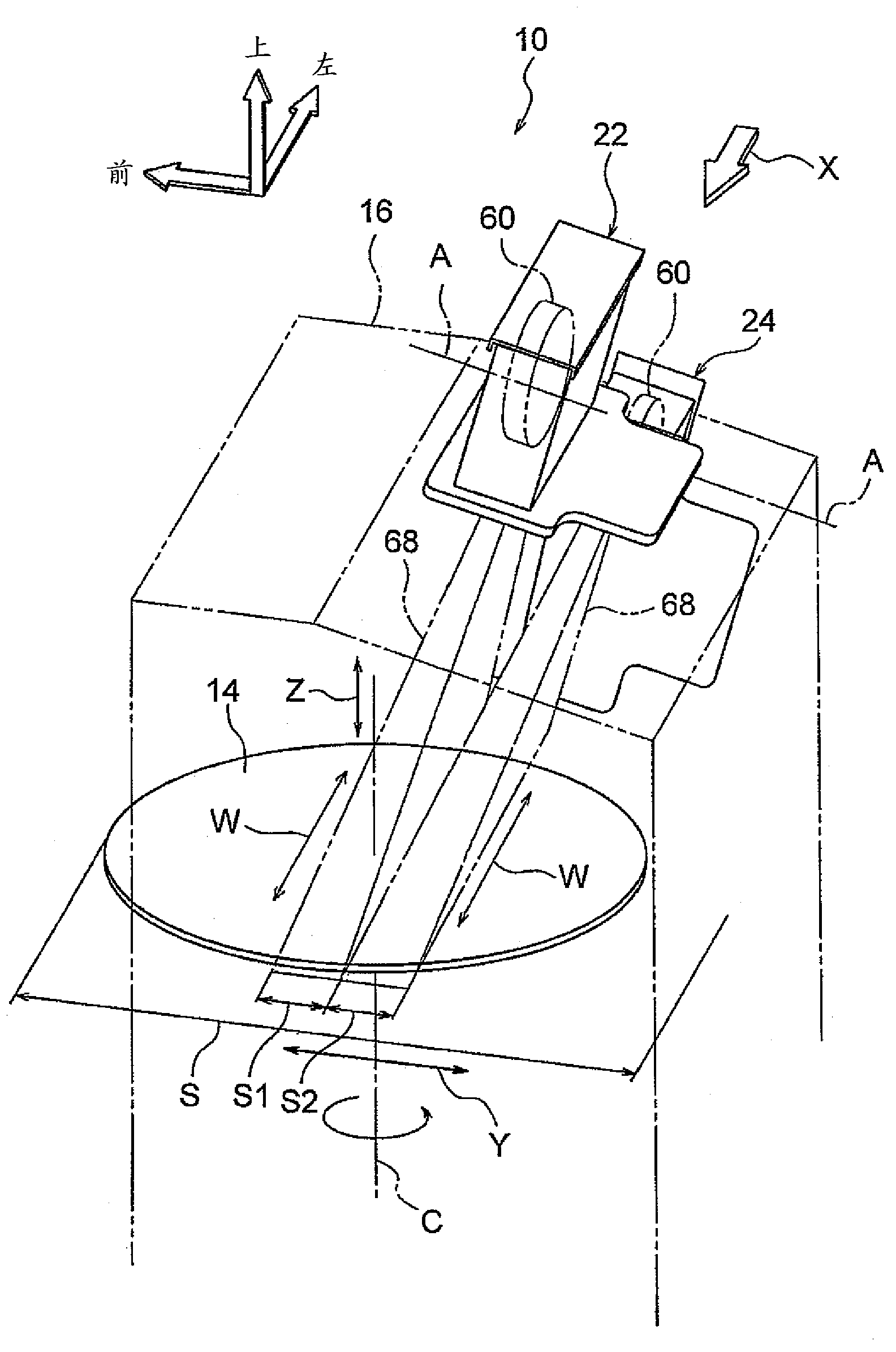
[0029] Such as figure 1 As shown, the shot peening apparatus 10 according to the first embodiment of the present invention is, for example, a shot peening apparatus used to remove scale attached to a metal workpiece 12, and the shot peening apparatus 10 includes a holding tool 14, The shot blasting chamber 16, the rotation drive part 18, the slide drive part 20, a pair of centrifugal projection machines 22 and 24, and the control part 26.

[0030] The holding tool 14 is formed in a disk shape and is arranged horizontally. A shaft portion 28 extending downward along the height direction of the shot blasting apparatus 10 is formed at a central portion on the back side of the holder 14 . Furthermore, the shaft par...


PUM


Abstract

This shot treatment device (10) is provided with: a holding jig (14) that is capable of rotating and sliding, and that holds a workpiece (12) on the axis of rotation; and a pair of centrifugal projectors (22, 24). The pair of centrifugal projectors: (22, 24) each have a rotatable impeller (60), the axis of rotation (A) of each impeller (60) being parallel to each other; are positioned offset to each other in the direction of the axes of rotation of the impellers (60); and are capable of projecting a projection material in parallel towards the workpiece (12) according to the rotation of the impellers (60). Since the offsetting of the projection material from one centrifugal projector (22) and the project material from the other centrifugal projector (24) is minimized by this configuration, the projection efficiency can be improved even when the projection material is projected from the pair of centrifugal projectors (22, 24).

Description

technical field [0001] The present invention relates to a shot peening device. Background technique [0002] Patent Document 1 discloses a shot blasting device equipped with a centrifugal projection machine at the upper and lower parts of a shot blasting chamber (cabinet). [0003] Patent Document 1: Japanese Patent No. 2868169 [0004] However, in the shot blasting device described in Patent Document 1, when projecting projected materials from each centrifugal projection machine, there are projected materials from the centrifugal projected machine equipped on the upper part of the shot blasting chamber and the projected material from the centrifugal projecting machine equipped in the shot blasting chamber. There is a concern that the projection materials of the lower centrifugal projection machine cancel each other out and the projection efficiency decreases. Contents of the invention [0005] This invention was made in view of the said subject, and it aims at providing...

Claims


Application Information

Patent Timeline
IPC IPC(8): B24C3/24B24C9/00
CPCB24C3/24B24C9/00
Inventor 山下恭司郑永荣铃木常俊山本卓司
Owner SINTOKOGIO LTD
Learn More