Base station device, terminal device, transmission method, and reception method
A terminal device and base station technology, applied in the direction of transmission path separation device, frequency division multiplexing system, orthogonal multiplexing system, etc., can solve the problem of unable to allocate CCE to PDCCH
- Summary
- Abstract
- Description
- Claims
- Application Information
AI Technical Summary
Problems solved by technology
Method used
Image

Examples
Embodiment approach 1
[0130] [Outline of Communication System]
[0131] The communication system of the present embodiment includes a base station 100 and a terminal 200 . The base station 100 is an LTE-A base station, and the terminal 200 is an LTE-A terminal.
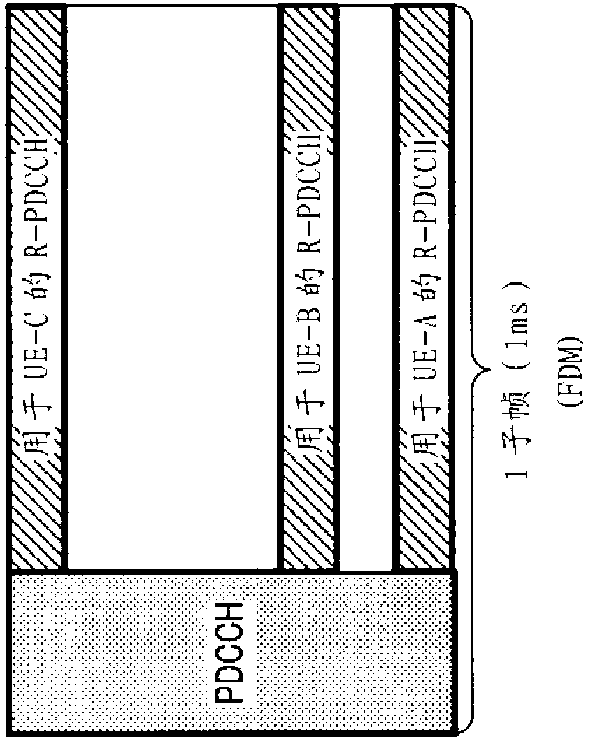
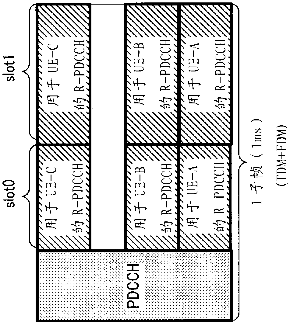
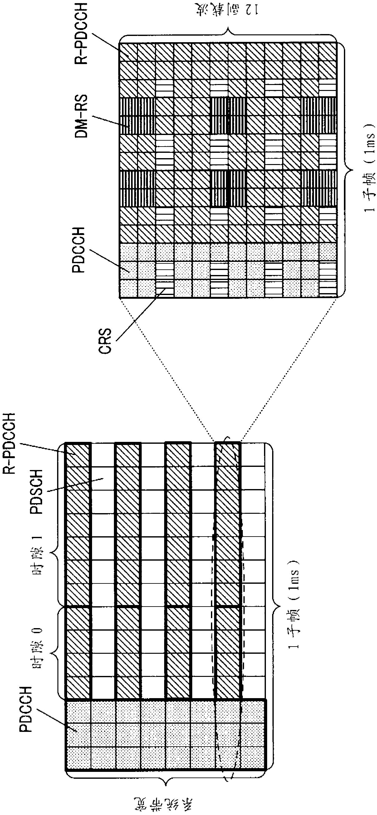
[0132] In the communication system of the present embodiment, allocation control information is transmitted from the base station 100 to the terminal 200 using the PDCCH and the R-PDCCH, the PDCCH uses the CRS which is a common reference signal that all terminals can receive, and the R-PDCCH uses the CRS or the CRS for each terminal. DM-RS of the dedicated reference signal.
[0133] Figure 4 The main components of the base station 100 according to the present embodiment are shown. exist Figure 4 In the illustrated base station 100, the search interval setting unit 103 configures a search interval having a plurality of DCI assignment area candidates in the PDCCH region and the R-PDCCH region, and the assignment unit 106 assigns assignme...
Embodiment approach 2
[0237] In Embodiment 1, the case where the terminal using the CRS and the terminal using the DM-RS coexist in the R-PDCCH region has been described. On the other hand, in the present embodiment, the case where the reference signal used by each terminal in the R-PDCCH region is fixedly set will be described.
[0238] Hereinafter, the setting methods 1 to 3 of the search area according to the present embodiment will be specifically described.
[0239] In addition, the basic structures of the base station and the terminal in this embodiment are the same as those in Embodiment 1, and therefore are cited Image 6 and Figure 8 Be explained.
[0240] In addition, in the following description, as in the first embodiment, as the C-SS, a total of 6 candidate DCI allocation areas with 4 candidates (16CCE) for the CCE aggregation number 4 and 2 candidates (16CCE) for the CCE aggregation number 8 are set as the C-SS (ie, blind decoding region candidates). In addition, as the UE-SS, 6 ...
Embodiment approach 3
[0280] In the present embodiment, a case where search intervals are set for each DCI format will be described.
[0281] In addition, the basic structures of the base station and the terminal in this embodiment are the same as those in Embodiment 1, and therefore are cited Image 6 and Figure 8 Be explained.
[0282] In addition, in the following description, as in the first embodiment, as the C-SS, a total of 6 candidate DCI allocation areas with 4 candidates (16CCE) for the CCE aggregation number 4 and 2 candidates (16CCE) for the CCE aggregation number 8 are set as the C-SS (ie, blind decoding region candidates). In addition, as the UE-SS, 6 candidates (6CCE), 6 candidates (12CCE), 2 candidates (8CCE), and 2 candidates (16CCE) corresponding to the CCE aggregation numbers of 1, 2, 4, and 8, respectively, are configured, totaling 16 Candidate DCI allocation regions (ie blind decoding region candidates). That is, a search interval (C-SS and UE-SS) composed of a total of 22...
PUM
 Abstract
Description
Claims
Application Information
 - R&D
- Intellectual Property
- Life Sciences
- Materials
- Tech Scout
- Unparalleled Data Quality
- Higher Quality Content
- 60% Fewer Hallucinations
Browse by: Latest US Patents, China's latest patents, Technical Efficacy Thesaurus, Application Domain, Technology Topic, Popular Technical Reports.
© 2025 PatSnap. All rights reserved.Legal|Privacy policy|Modern Slavery Act Transparency Statement|Sitemap|About US| Contact US: help@patsnap.com