Automatic rib rolling machine

A kind of rolling bar machine, automatic technology, applied in metal processing equipment, forming tools, manufacturing tools and other directions, can solve problems such as unfavorable gear mechanism meshing, spring deformation, cam drive shaft swing, etc., to reduce labor intensity, save time, The effect of avoiding gear meshing problems

Active Publication Date: 2013-03-27
ZIBO YONGHUA FILTERS MAKE
View PDF9 Cites 2 Cited by
  • Summary
  • Abstract
  • Description
  • Claims
  • Application Information

AI Technical Summary

Problems solved by technology

[0002] The roller rib machine is widely used in the manufacturing process of filter equipment. The existing motor for the roller rib machine drives the concave-convex mold to rotate through two shafts through gear reduction. However, during the rotation process, the handle at the upper end of the shaft side needs to be adjusted to adjust the height of the cam. In order to control the depth of the bead on the round tube, the spring support in the middle of the two shafts is required during the beading process. Long-term use will cause the deformation of the spring, and it is easy to cause the cam to adjust the height of the cam to control the depth of the bead on the round tube. The transmission shaft of the drive shaft swings, which is not conducive to the meshing of the gear mechanism, and it is time-consuming and labor-intensive

Method used


Image

  • Automatic rib rolling machine
  • Automatic rib rolling machine

Examples


Embodiment Construction

[0015] Embodiments of the present invention are further described below in conjunction with accompanying drawings:

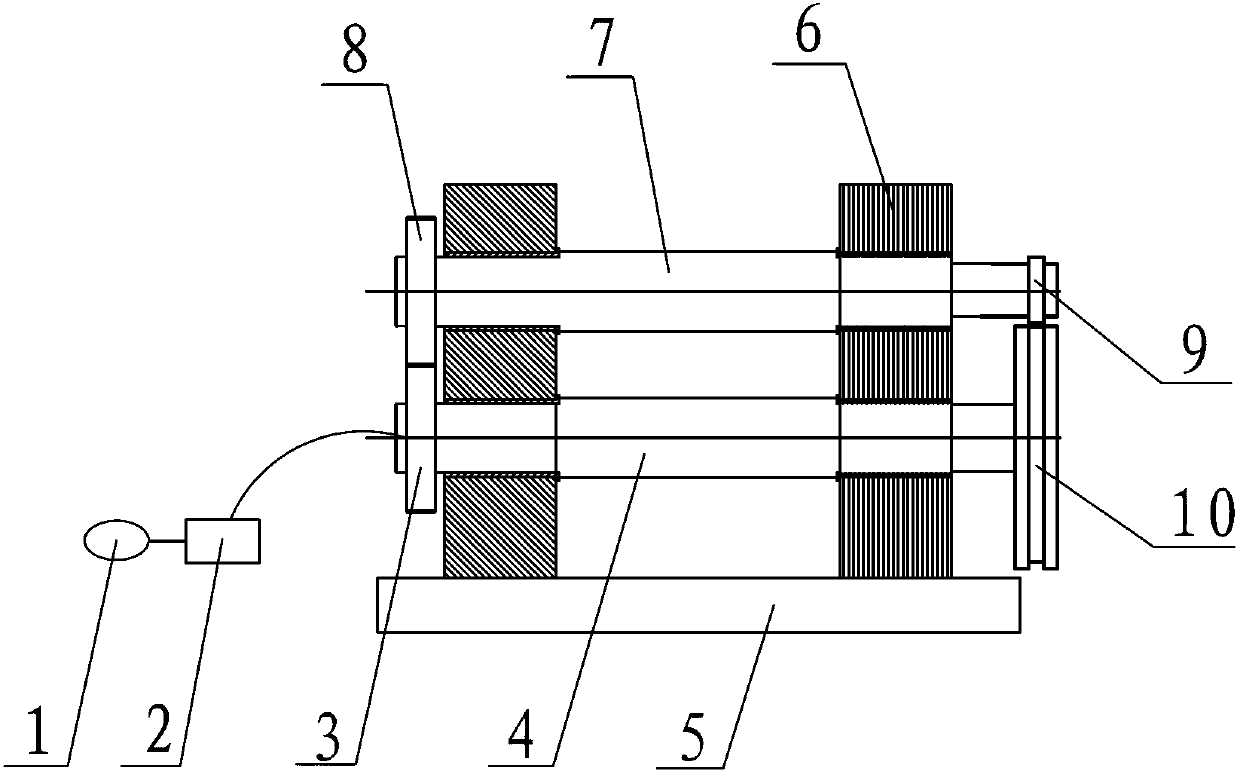
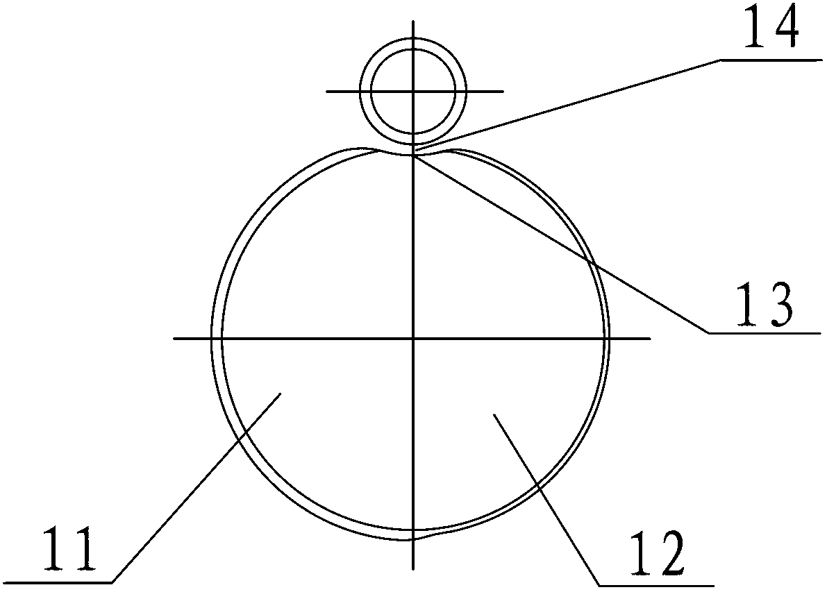
[0016] Such as Figure 1-2 As shown, the automatic rolling machine includes a motor 1, a gearbox 2, a first transmission shaft 4, a second transmission shaft 7, a first gear 3, a second gear 8 and a base 5, the motor 1 is connected to the gearbox 2, and the gearbox 2 connected to the first transmission shaft 4, the first gear 3 is installed on one end of the first transmission shaft 4, the first gear 3 meshes with the second gear 8, the second gear 8 is connected to one end of the second transmission shaft 7, the first transmission shaft 4 and the second transmission shaft 7 are fixed by the fixed plate 6 installed on the base 5, the second transmission shaft 7 is connected to the male mold 9 at the end away from the second gear 8, and the first transmission shaft 4 is connected to the female mold 10 at the end away from the first gear 3 , the male die 9 corres...


PUM

PropertyMeasurementUnit
radiusaaaaaaaaaa
radiusaaaaaaaaaa
depthaaaaaaaaaa

Abstract

The invention relates to a rib rolling machine, and in particular relates to an automatic rib rolling machine which belongs to the field of manufacturing of filter devices. The automatic rib rolling machine is characterized in that a first transmission shaft (4) and a second transmission shaft (7) are fixedly arranged through fixed plates (6) installed on a base (5); the end, far from a second gear (8), of the second transmission shaft (7) is connected with a convex die (9), and the end, far from a first gear (3), of the first transmission shaft (4) is connected with a concave die (10); and the convex die and the concave die correspond to each other. The concave die is in a secondary advanced cam-like structure. With the adoption of a motor, through gear reduction, the two transmission shafts drive the convex and concave dies to rotate, and manual regulation is replaced by changing the radius of the concave die. In the anticlockwise rotating process, the convex and concave dies pass through a first semi-circle and a second semi-circle in sequence, a workpiece is prevented from being torn due to excessive rolling at one time. The two transmission shafts are fixedly arranged, so that the gear engagement problem is effectively avoided, the time is saved, and the labor intensity of workers is greatly reduced.

Description

technical field [0001] The invention relates to a rib rolling machine, in particular to an automatic rib rolling machine, which belongs to the field of filter equipment manufacturing. Background technique [0002] The roller rib machine is widely used in the manufacturing process of filter equipment. The existing motor for the roller rib machine drives the concave-convex mold to rotate through two shafts through gear reduction. However, during the rotation process, the handle at the upper end of the shaft side needs to be adjusted to adjust the height of the cam. In order to control the depth of the bead on the round tube, the spring support in the middle of the two shafts is required during the beading process. Long-term use will cause the deformation of the spring, and it is easy to cause the cam to adjust the height of the cam to control the depth of the bead on the round tube. The transmission shaft of the machine has a swing, which is not conducive to the meshing of the...

Claims


Application Information

Patent Timeline
Patent Type & Authority Applications(China)
IPC IPC(8): B21D15/00B21D37/10
Inventor 李永华周广超徐庆和桑志强
Owner ZIBO YONGHUA FILTERS MAKE
Why Eureka
Try Eureka