Rotatable fixing device and lighting equipment with same

A technology for fixing devices and lighting equipment, which is applied in the direction of fixing lighting devices, lighting and heating equipment, parts of lighting devices, etc., and can solve problems such as wear and tear, difficulty in maintaining down-mounted lights, etc.

Inactive Publication Date: 2012-04-04
OSRAM GMBH
View PDF0 Cites 1 Cited by
  • Summary
  • Abstract
  • Description
  • Claims
  • Application Information

AI Technical Summary

Problems solved by technology

But after adjusting the irradiation angle of the ceiling light many times, there will also be wear and tear between

Method used


Image

  • Rotatable fixing device and lighting equipment with same
  • Rotatable fixing device and lighting equipment with same
  • Rotatable fixing device and lighting equipment with same

Examples


Embodiment Construction

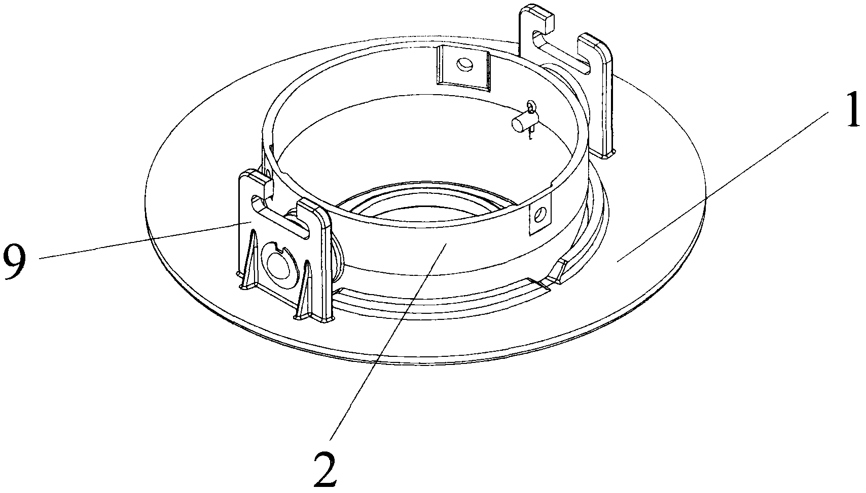
[0020] figure 1 A schematic diagram showing a swivel fixture according to the invention fitted to a lighting device. exist figure 1 It can be seen that the lighting equipment has: an assembly ring 1, which is used to fix the lighting equipment at a predetermined installation position; a rotating ring 2, which is used to fix the light emitting elements of the lighting equipment, such as LED modules; 2 between the rotating fixing device, through which the rotating ring 2 can rotate relative to the assembly ring 1, and after rotating to a predetermined angle, it is locked at the angle. It can be seen from the figure that two brackets 9 are arranged on the diametrically opposite sides of the assembly ring 1, and one side of the two rotating fixtures is installed on the two brackets 9 respectively, and the other side is installed on the rotating ring 2 .

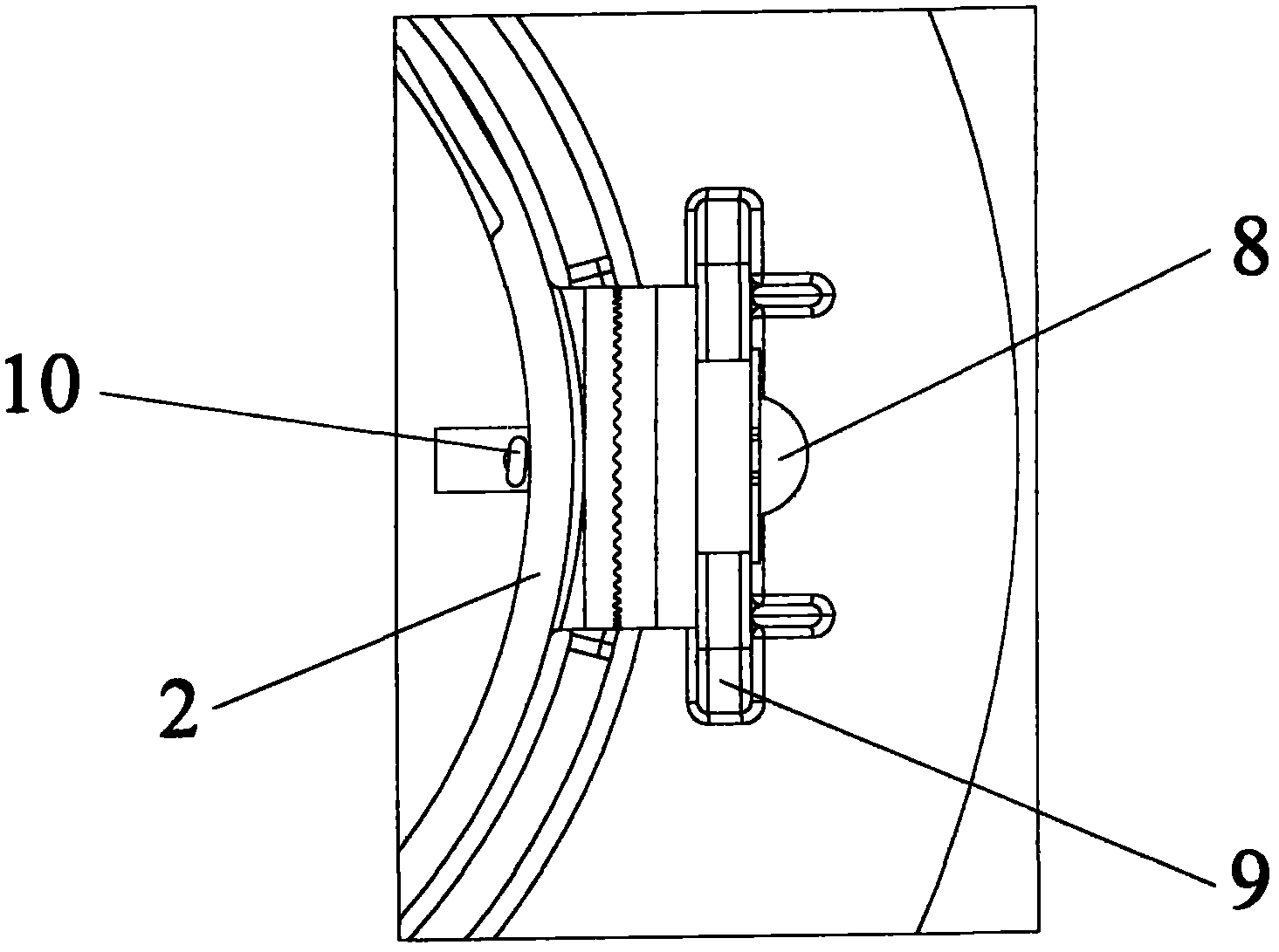
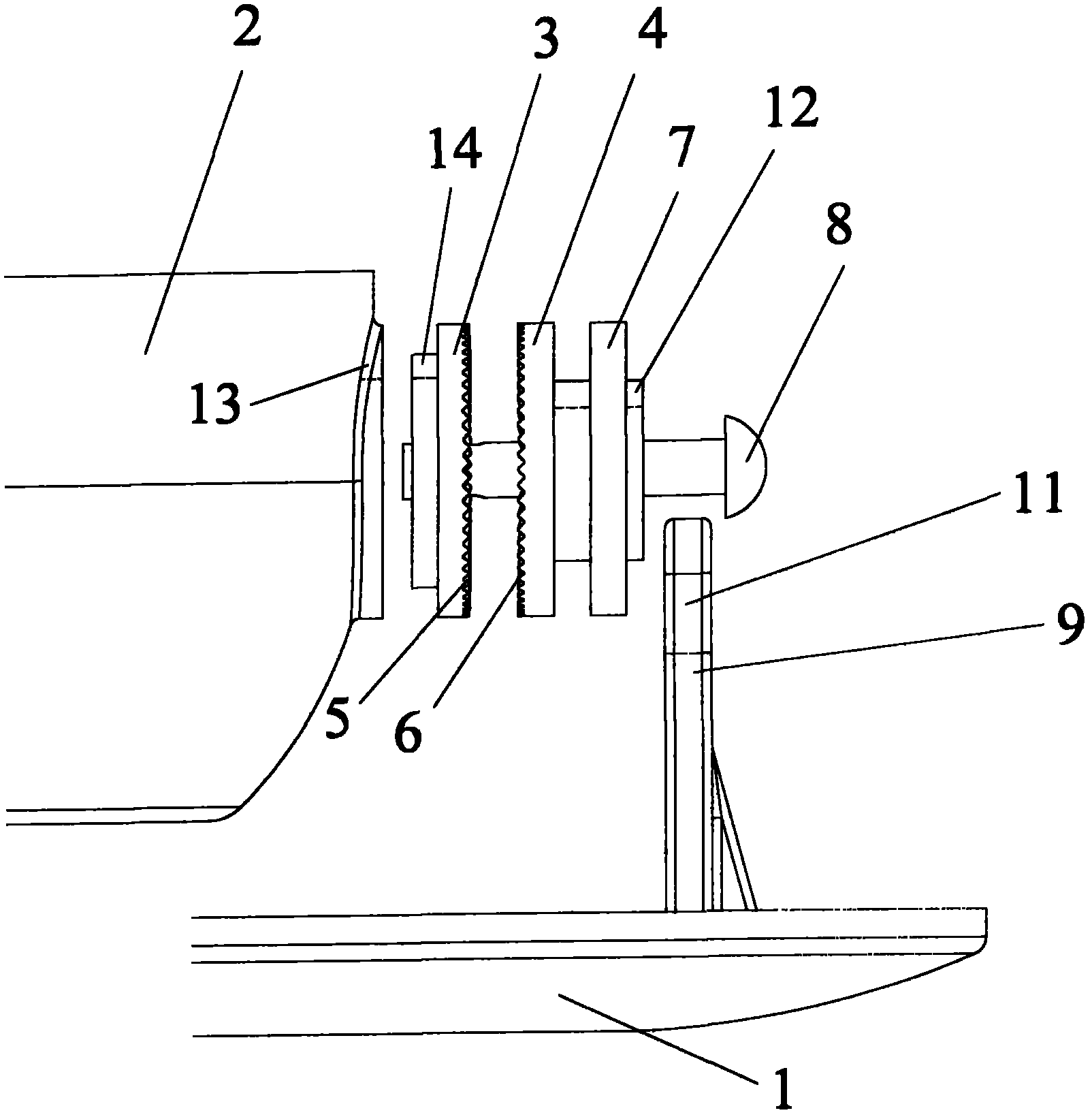
[0021] figure 2 is a schematic diagram of the rotation fixture according to the present invention on one side of the light...


PUM


Abstract

The invention relates to a rotatable fixing device for lighting equipment. The lighting equipment is provided with a fixedly arranged assembling ring (1) and a rotatable ring (2) which rotates relative to the assembling ring (1). The rotatable fixing device is provided with a first disc (3) which is connected with the rotatable ring (2) in an anti-torsion way and a second disc (4) which is connected with the assembling ring in an anti-torsion way, wherein the first disc (3) and the second disc (4) is respectively provided with a first tooth part (5) and a second tooth part (6). The locking of the rotating angle of the lighting equipment is realized through the engagement between the first tooth part (5) and the second tooth part (6), and the adjustment of the rotating angle of the lighting equipment is realized through the disengagement between the first tooth part (5) and the second tooth part (6). By using the rotatable fixing device, the lighting equipment can be reliably fixed at a preset illumination angle and the service life of the entire lighting equipment is not reduced when the times of angle adjustment are increased. Besides, the invention additionally relates to the lighting equipment with the rotatable fixing device.

Description

technical field [0001] The present invention relates to a rotary fixing device for lighting equipment, especially LED lighting equipment, which may be hidden LED lighting equipment, such as a downlight. In addition, the present invention also relates to a lighting device having a rotary fixing device of the above-mentioned type. Background technique [0002] Today's lighting fixtures, especially LED lighting fixtures, are often applied as downlights. This type of downlight usually needs to be illuminated in different directions according to the needs of lighting. Depending on their power, such LED lighting devices are equipped with cooling bodies for heat dissipation. High-power LED lighting devices are usually equipped with heavy cooling bodies. In order to enable the LED lighting equipment to illuminate in a fixed direction, it needs to be adjusted to a certain angle and kept at this angle. [0003] One solution in the prior art is to mount the ceiling light on the mou...

Claims


Application Information

Patent Timeline
IPC IPC(8): F21V21/14F21V21/18F21S8/04
CPCF21S8/026F21V21/30
Inventor 黄茜陈友肖尚平李皓
Owner OSRAM GMBH
Why Eureka
Try Eureka