Punching die of vacuum booster upper push rod assembly

A technology of vacuum booster and push rod, which is applied in the direction of piercing tools, manufacturing tools, and pushing equipment, etc., which can solve the troublesome problems of waste disposal

Active Publication Date: 2013-03-27
浙江汇丰汽车零部件股份有限公司
View PDF6 Cites 8 Cited by
  • Summary
  • Abstract
  • Description
  • Claims
  • Application Information

AI Technical Summary

Problems solved by technology

[0002] The push rod assembly on the car vacuum booster is the output part of the vacuum booster. One end of it is connected to the car pedal bracket, and the other end is connected to the pedal bracket through a fork. The fork includes two connecting arms. Each Each connecting arm is provided with a through hole punched out by a punching die. Because there is a gap between the two connecting arms, the traditional punching die will easily break, deform or damage the two arms of the fork, and It adopts the method of secondary stamping, that is, it needs two times of clamping and stamping to complete. Since the two arms of the push rod assembly are separated, it is more troublesome to deal with the waste generated by punching, which is helpful for the vacuum of the car. The punching efficiency and quality of the push rod assembly on the vacuum resistor have a great influence, and the one-time punching of the push rod assembly on the vacuum resistor has always been a difficult problem

Method used


Image

  • Punching die of vacuum booster upper push rod assembly
  • Punching die of vacuum booster upper push rod assembly
  • Punching die of vacuum booster upper push rod assembly

Examples


Embodiment 1

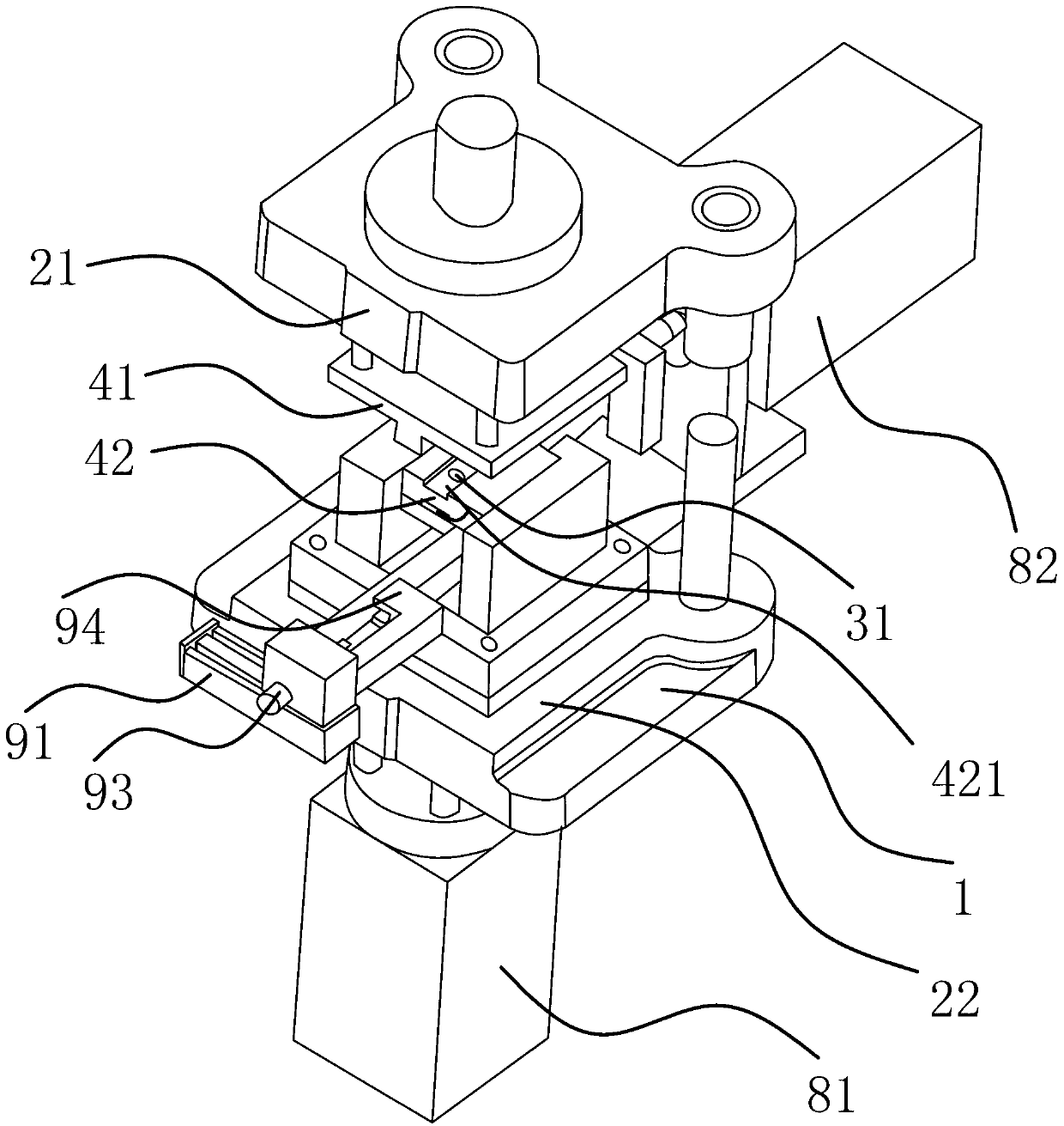
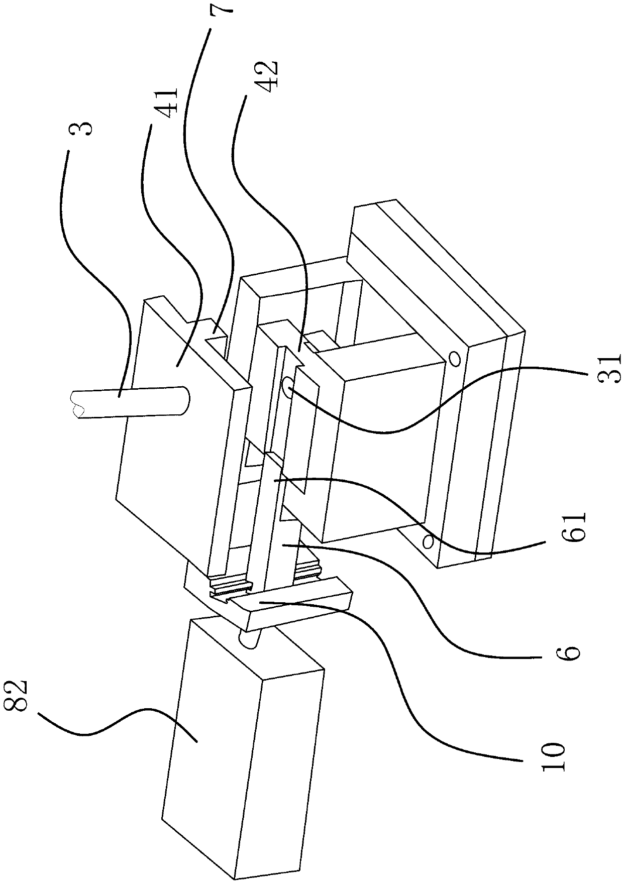
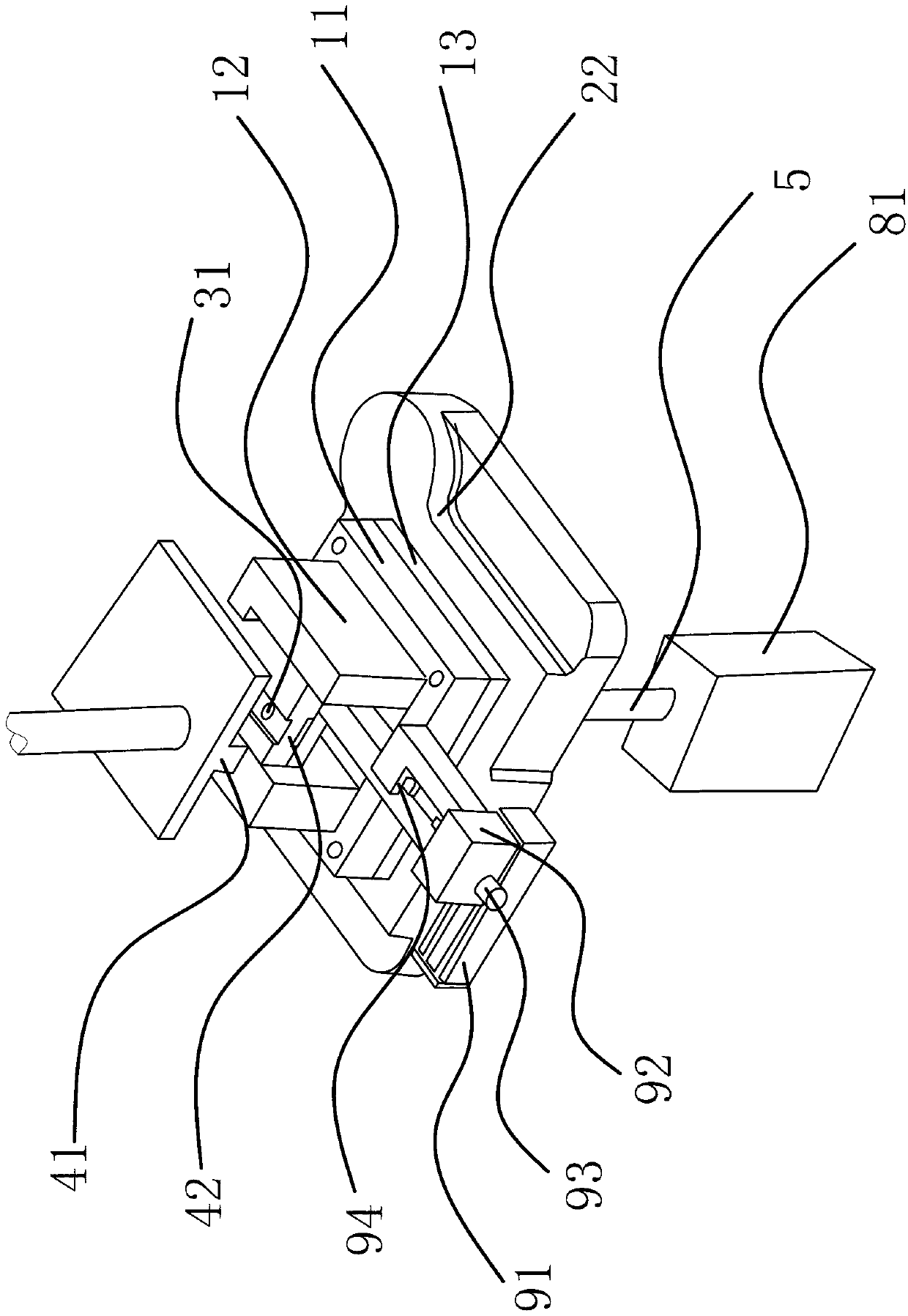
[0026] Such as figure 1 , figure 2 , image 3 and Figure 4 As shown, this punching die comprises frame 1, upper mold base 21, punch 3, and horizontally arranged punch 41 and die 42, and the upper surface and lower surface of die 42 are respectively provided with a connected bar-shaped groove 421, the punch 3 is arranged on the upper die base 21 in the vertical direction and is facing the bar-shaped groove 421, and the punch 41 and the die 42 are provided with the punch 3 directly below and allow The through hole 31 that the punch 3 passes through, the lower end of the frame 1 is provided with a waste push rod 5 that pushes away the waste generated by the workpiece from the die 42 after the punching is completed, and the rear end of the frame 1 is provided with a The workpiece can be pushed away from the ejector push rod 6 of the die 42, and the punch 41 is provided with an alignment plate 7, which can lean against the bar-shaped groove 421 on the upper surface of the die ...

Embodiment 2

[0030] Such as figure 2 and Figure 6 As shown, the content of this embodiment is roughly the same as that of Embodiment 1, except that the ejector structure includes a support arm 2 95 fixed on the frame 1 and a slider 2 96 that can slide back and forth on the support arm 2 95 The slider 2 96 is located directly in front of the bar-shaped groove 421, and the slider 2 96 is provided with a notch 97 that can be sleeved on one end of the workpiece to hold the workpiece up. The end of the connecting rod 14 of the workpiece is against the In the notch 97, slide block 2 96 and support arm 2 95 belong to a tight fit, and slide block 2 96 will not loosen after adjusting the position with the strip groove 421. Pushing slide block 2 96 back and forth makes the workpiece The two connecting arms 15 abut against the strip-shaped groove 421 .

[0031] The working principle of this punching die is: the workpiece mentioned in this manual refers to the upper push rod assembly of the vacuum...


PUM


Abstract

The invention discloses a punching die of a vacuum booster upper push rod assembly and belongs to the technical field of dies. The punching die of the vacuum booster upper push rod assembly solves the problem that an existing punching die of the vacuum booster upper push rod assembly cannot complete punching once and cause deformation or breakage and the like of a connecting arm of a push rod assembly easily. The punching die comprises a machine frame, an upper die base, a punch pin, a male die and a female die, wherein the male die and the female die are arranged horizontally. One strip-shaped groove capable of being clamped with a workpiece is respectively arranged on the upper surface and the lower surface of the female die, a punch pin is arranged on the upper die base vertically and faces to the strip-shaped groove, the male die and the female die are provided with through holes which are located below the punch pin and allow the punch pin to penetrate through, a waste material push rod for pushing waste materials generated by the workpieces away from the female die after punching is finished is arranged at the lower end of the machine frame, and a material returning push rod capable of pushing the workpieces away from the female die is arranged at the lower end of the machine frame. The punching die of the vacuum booster upper push rod assembly has the advantages of being high in punching efficiency, high in finished product rate, high in automation degree and the like.

Description

technical field [0001] The invention belongs to the technical field of moulds, and relates to a punching die, in particular to a punching die for a push rod assembly on a vacuum booster. Background technique [0002] The push rod assembly on the car vacuum booster is the output part of the vacuum booster. One end of it is connected to the car pedal bracket, and the other end is connected to the pedal bracket through a fork. The fork includes two connecting arms. Each Each connecting arm is provided with a through hole punched out by a punching die. Since there is a gap between the two connecting arms, the traditional punching die will easily break, deform or damage the two arms of the fork. It adopts the method of secondary stamping, that is, it needs two times of clamping and stamping to complete. Since the two arms of the push rod assembly are separated, it is more troublesome to deal with the waste generated by punching, which is helpful for the vacuum of the car. The pu...

Claims


Application Information

Patent Timeline
IPC IPC(8): B21D28/34B21D45/02
Inventor 董西杰董服友林成明
Owner 浙江汇丰汽车零部件股份有限公司
Why Eureka
Try Eureka