
Method for producing a wind turbine rotor blade part with a prefabricated main spar cap

一种风力涡轮机、制造方法的技术,应用在与风向一致的的风力发动机、风力发动机、发动机元件等方向,能够解决增大转子叶片重量、高负载等问题

Inactive Publication Date: 2013-03-27
NORDEX ENERGY
View PDF2 Cites 6 Cited by
  • Summary
  • Abstract
  • Description
  • Claims
  • Application Information

AI Technical Summary

Problems solved by technology

This significantly increases the weight of the rotor blade and, in particular, higher loads occur in the region of the connection of the rotor blade to the hub

Method used


Image

  • Method for producing a wind turbine rotor blade part with a prefabricated main spar cap
  • Method for producing a wind turbine rotor blade part with a prefabricated main spar cap

Examples


Embodiment Construction

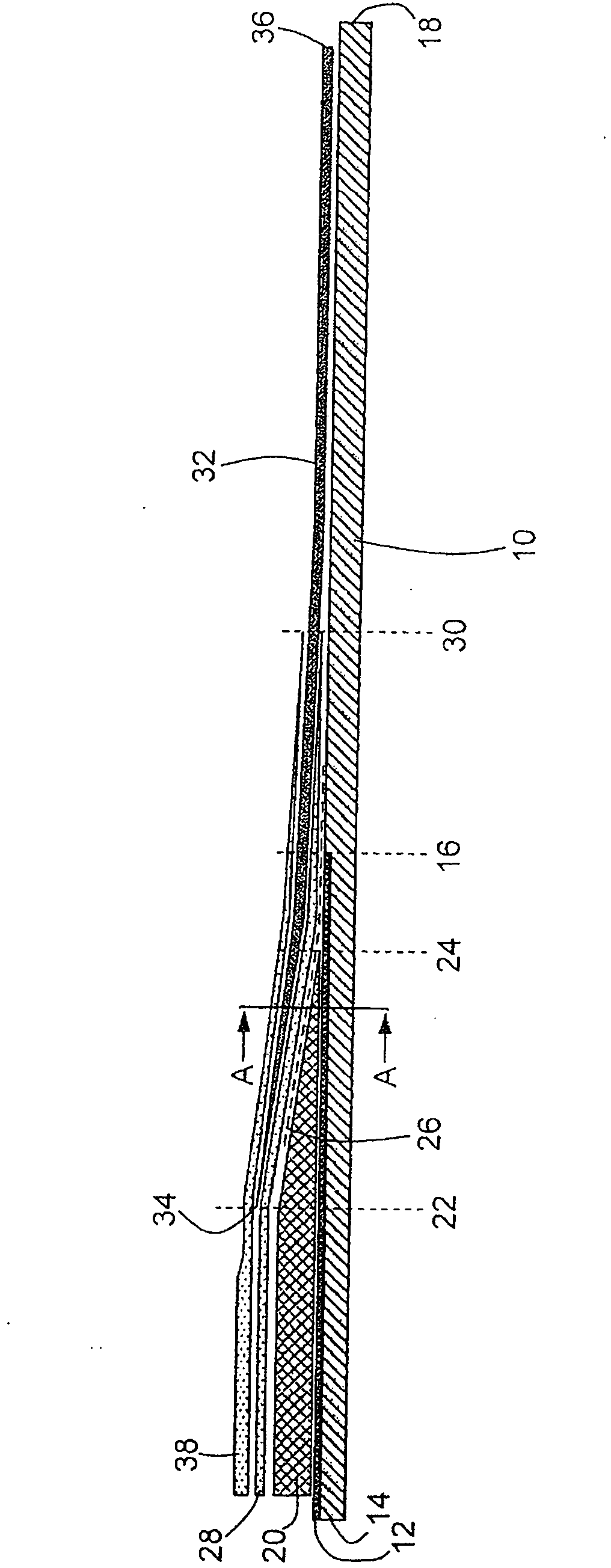
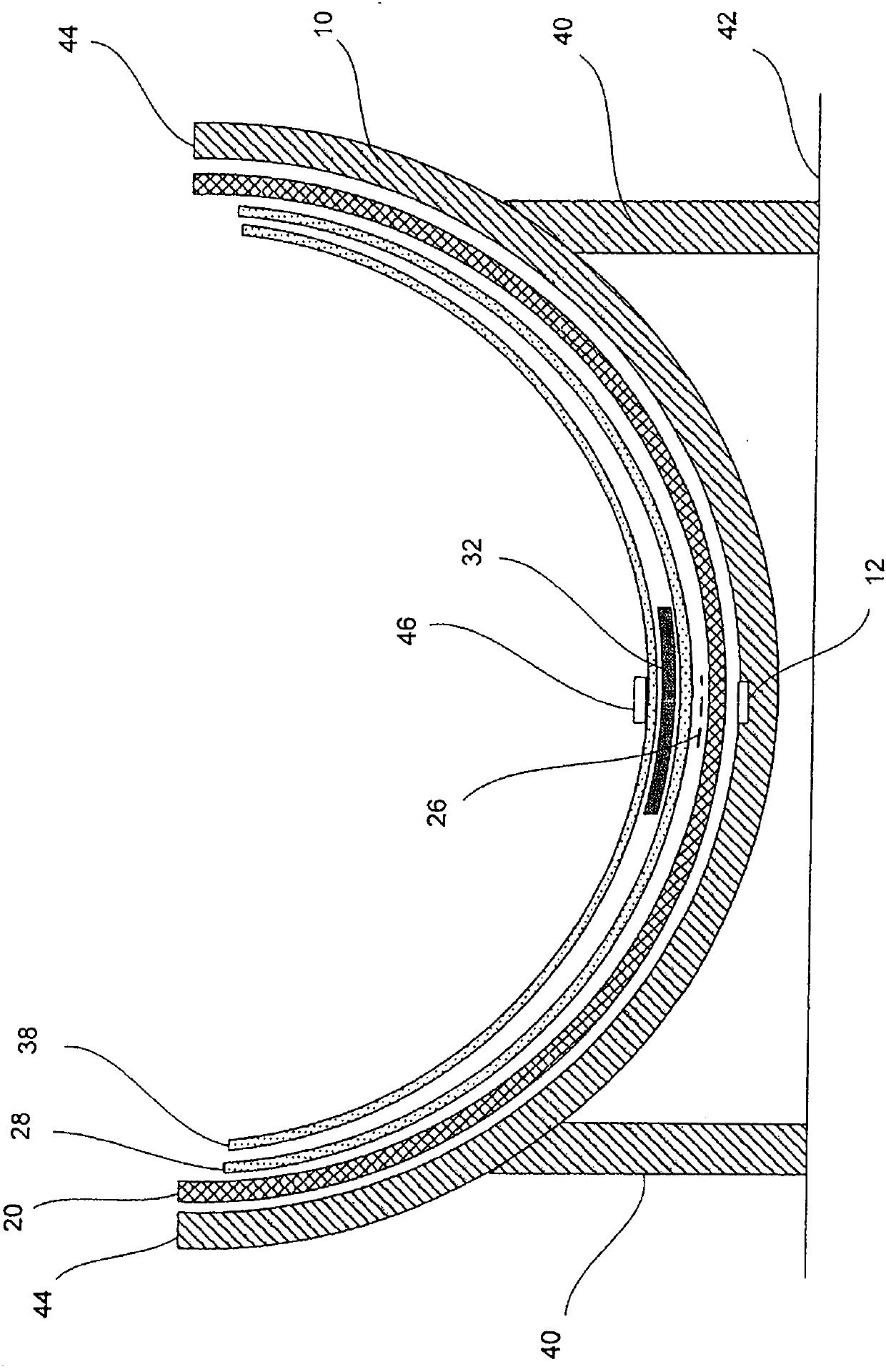
[0050] figure 1 A mold 10 for manufacturing a wind turbine rotor blade component is shown. The mold 10 has a first sprue 12 extending from a blade root end 14 of the mold to a first radial location 16 . The end of the mold 10 opposite the blade root end 14 is referred to as the blade tip 18 .

[0051] Root insert 20 is inserted into mold 10 and is prefabricated from 50 to 70 or more layers of fiberglass material. The outside of the root insert 20 is in direct contact with the inside of the mold 10 . The root insert 20 extends to near the blade root end 14 of the mold 10 where its end forms the blade root end of the finished wind turbine rotor blade component. The root insert 20 is initially uniform in thickness near the blade root end 14 and then tapers in a wedge-shaped fashion beginning at a second radial position 22 until the root insert 20 finally terminates at a third radial position 24 .

[0052] Above the root insert 20 there is provided a distribution medium 26 , w...


PUM


Abstract

Method for producing a wind turbine rotor blade part with a prefabricated main spar cap, comprising the following steps: providing a mold having a blade-root end and with a blade-tip end, inserting at least one outer root reinforcement layer (28) made of a fibrous material into the mold, arranging the prefabricated main spar cap on the at least one outer root reinforcement layer, arranging, in the mold, at least one inner root reinforcement layer made of a fibrous material on the main spar cap, closing the mold, extracting the air from the mold through at least one extraction channel arranged at a lateral distance from the main spar cap, feeding a liquid plastics material through a first sprue channel which has a plurality of outlet openings below the main spar cap, feeding a liquid plastics material through a second sprue channel which has a plurality of outlet openings above the main spar cap.

Description

technical field [0001] The invention relates to a method of manufacturing a wind turbine rotor blade component with a prefabricated main spar cap. Wind turbine rotor blades are usually manufactured from a combination of fiber reinforced plastic materials, such as glass fibers, with polyester or epoxy resins. Background technique [0002] Publication EP0525263A1 discloses a vacuum introduction process for manufacturing fibre-reinforced plastic parts. In this known process, layers of fiber material are inserted into a mould. Below and above these fibrous material layers, respectively, a distribution medium is provided which is separated from those fibrous material layers by a plurality of further layers made of plies known as exfoliated plies. On the bottom side of the mould, injection channels are provided below the lower distribution medium and suction channels are provided above the upper distribution medium. The airtight mold is evacuated through the suction channel and...

Claims


Application Information

Patent Timeline
Patent Type & Authority Applications(China)
IPC IPC(8): B29C70/34B29C70/54
CPCF03D1/0675F05B2280/702B29C70/44F03D1/065B29L2031/082B29C70/546F05B2280/6003F05B2280/6015Y02E10/721B29C70/865Y02E10/72Y02P70/50
Inventor M·弗兰科斯基D·奥斯蒂纳特
Owner NORDEX ENERGY
Learn More