Pulling-rope positioning and control method, device and system

A technology of positioning control and pose information, applied to mechanically driven excavators/dredgers, etc., can solve problems such as large installation errors, heavy workload, and low work efficiency, and achieve improved test accuracy, accurate anchoring positions, and reduced effect of error

Active Publication Date: 2013-03-27
ZOOMLION HEAVY IND CO LTD
View PDF4 Cites 13 Cited by
  • Summary
  • Abstract
  • Description
  • Claims
  • Application Information

AI Technical Summary

Problems solved by technology

[0005] In the prior art, the fixed position of the stay rope on the anchor frame is usually determined visually or manually by the tester, which often leads to large installation errors, so that the stay rope is not set along the tangential direction of the exc

Method used


Image

  • Pulling-rope positioning and control method, device and system
  • Pulling-rope positioning and control method, device and system
  • Pulling-rope positioning and control method, device and system

Examples


Embodiment Construction

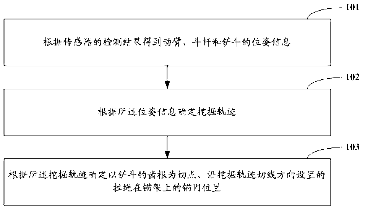
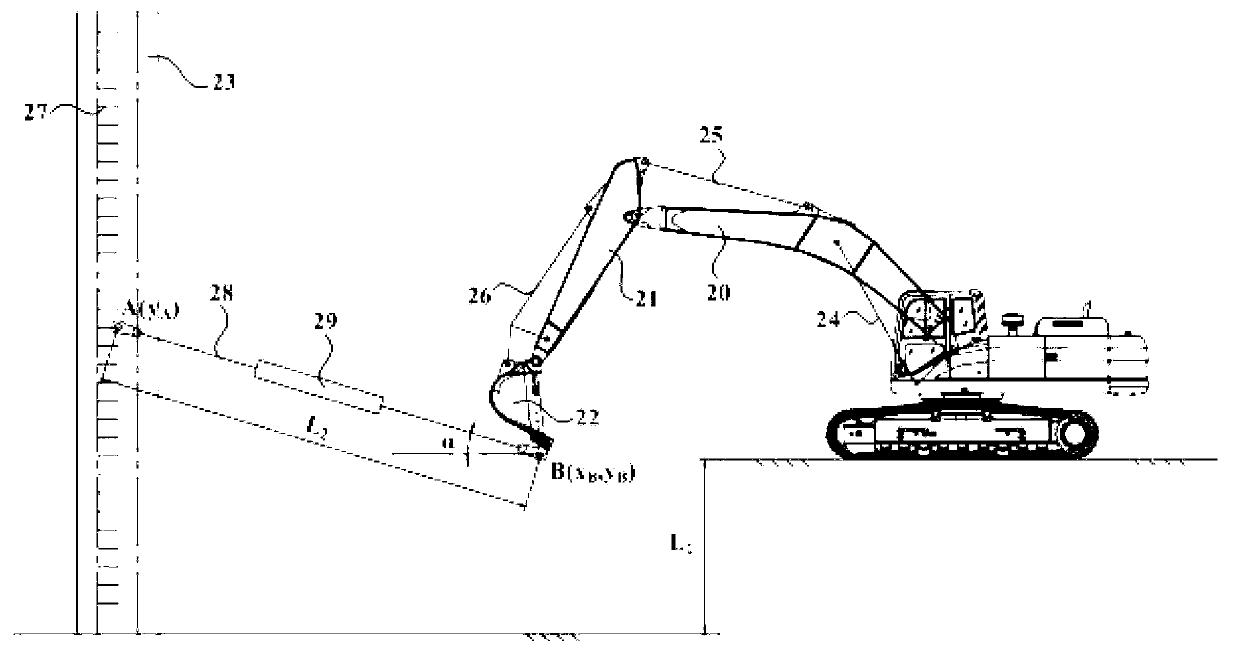
[0027] In order to improve the test accuracy of the digging force test of the excavator, the present invention provides a pull rope positioning control method, device and system applied to the digging force test of the excavator. The position and orientation information of the pole and bucket, the control device determines the excavation trajectory according to the position and orientation information, and finally obtains the anchoring position of the stay rope on the anchor frame. The determination of the anchoring position is relatively accurate, which greatly improves the test accuracy of the excavation force test. In order to make the purpose, technical solution and advantages of the present invention clearer, the following specific examples are given to further describe the present invention in detail.

[0028] Such as figure 1 As shown, the present invention is applied to an embodiment of the stay rope positioning control method for excavator excavation force testing, in...


PUM


Abstract

The invention relates to the technical field of earthmoving machines and discloses a pulling-rope positioning and control method, device and system applied to excavating-force test of an excavator. The method comprises the following steps of: obtaining position information of a movable arm, a bucket rod and a shoveling bucket according to a detected result of a sensor; and determining the excavating track according to the position information; determining that a tooth root of the shoveling bucket is used as a tangential point according to the excavating track and a pulling rope arranged along the tangential direction of the excavating track is fixed on the anchoring position on an anchor frame. Compared with the prior art, the technical scheme of the invention has the advantages that the errors caused by artificial visual inspection or manual measurement are greatly reduced, the anchoring position of the pulling rope on the anchor frame is more accurate and the testing accuracy of the excavating force test is greatly increased.

Description

technical field [0001] The invention relates to the technical field of earth-moving machinery, in particular to a pull rope positioning control method, device and system applied to excavator digging force testing. Background technique [0002] An excavator, also known as an excavator, is an earth-moving machine that uses a bucket to excavate materials that are higher or lower than the bearing surface and load them into transport vehicles or unload them to the stockyard. Excavators usually include a working device, an upper turntable and a traveling mechanism. The working device is a device that directly completes the excavation task, including a boom, a stick and a bucket. The angle between the two, the arm and the bucket are hinged, and the angle between the two is changed by the action of the bucket cylinder. [0003] Digging force is one of the important indicators to measure the digging performance of excavators, and it is also the basis for structural design and streng...

Claims


Application Information

Patent Timeline
IPC IPC(8): E02F3/28
Inventor 王惠科刘小华戴呈豪朱俊辉王敏捷
Owner ZOOMLION HEAVY IND CO LTD
Why Eureka
Try Eureka