S-shaped curve based method for control track of shield tunneling machine

A trajectory control and shield machine technology, which is applied in earthwork drilling, mining equipment, tunnels, etc., can solve problems such as difficulty in implementation, low sensitivity, and inability to ensure that the posture of the shield machine is completely consistent with the design axis, etc.

Active Publication Date: 2013-03-27
SHANGHAI TONGYAN CIVIL ENGINEERING TECHNOLOGY CORP LTD
View PDF6 Cites 21 Cited by
  • Summary
  • Abstract
  • Description
  • Claims
  • Application Information

AI Technical Summary

Problems solved by technology

In shield construction, the smaller the deviation between the shield machine track and the design axis, the smoother the curve, the higher the construction quality. The volatility of the trajectory, and the lack of good control of the return of the shield machine to the design axis position
Discuss the deviation correction of straight line, circular curve, and transitional curve separately. Using transitional curve as the deviation correction line type requires iteration in the calculation, the calculation formula is complicated, the realization is difficult, and the calculation result is difficult to guarantee; the fuzzy control method is introduced, and its fuzzy control The table is usually selected according to experience, the sensitivity is low, and the position deviation and angle deviation of the shield machine cannot be corrected at the same time; the attitude trajectory composite method assumes that the tunnel design axis can be regarded as a straight line, so the attitude of the shield machine cannot be guaranteed in the curved section Exactly coincides with the design axis

Method used


Image

  • S-shaped curve based method for control track of shield tunneling machine
  • S-shaped curve based method for control track of shield tunneling machine
  • S-shaped curve based method for control track of shield tunneling machine

Examples


Embodiment

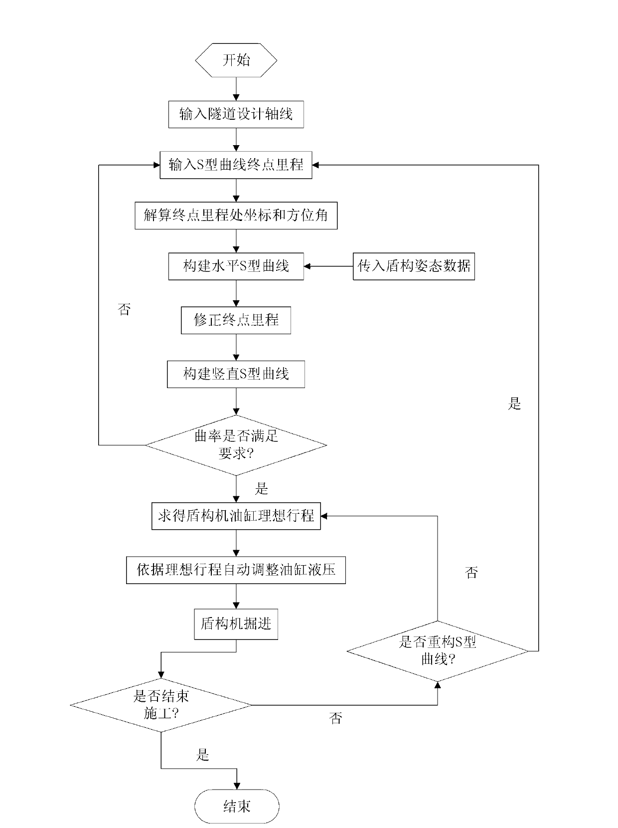
[0061] like figure 1 As shown, a shield machine trajectory control method based on S-curve, the method includes the following steps:

[0062] 1) The computer obtains the horizontal and vertical curve elements of the tunnel design axis, and discretizes them into end-to-end line elements, and the line elements include straight lines, transitional curves and circular curves. Described discretization into end-to-end line elements refers to obtaining the basic parameters of each line element and the mileage of each line element starting point and end point; for straight line elements, its basic parameters include starting point coordinates and end point coordinates; for transitional curves Its basic parameters include starting point coordinates, starting point azimuth, clothoid parameters, curve length and type; for circular curves, its basic parameters include circle center coordinates, starting angle, end point angle and arc radius.

[0063] 2) The computer obtains the initially...


PUM


Abstract

The invention relates to an S-shaped curve based method for control a track of a shield tunneling machine. The method comprises the steps of obtaining horizontal and vertical curve elements of a tunnel design axis; obtaining mileages of terminal points of S-shaped curves, which are set initially; calculating coordinates and azimuth angles at positions of mileages of terminal points of S-shaped curves; obtaining real-time attitude data of the shield tunneling machine; establishing the horizontal S-shaped curve; correcting mileages of terminal points of S-shaped curves; establishing the vertical S-shaped curve; judging whether the minimum curvature radiuses of S-shaped curves are less than the minimum turning radius of the shield tunneling machine or not, and obtaining mileages of terminal points of S-shaped curves again if the minimum curvature radiuses of S-shaped curves are less than the minimum turning radius of the shield tunneling machine; calculating an ideal stroke of a jack after the shield tunneling machine tunnels one ring along S-shaped curves; converting data of the ideal stroke into the required oil cylinder hydraulic pressure; and transmitting calculation results to the shield tunneling machine by a computer, controlling the shield tunneling machine to tunnel forward, and judging in real time whether S-shaped curves are required to be reconstructed or not. Compared with the prior art, the method has the advantages of being capable of finishing deviation rectification once, high in generality, capable of reducing the fluctuation of the track of the shield tunneling machine and the like.

Description

technical field [0001] The invention relates to a tunnel driving control method, in particular to an S-curve-based shield machine trajectory control method. Background technique [0002] In shield construction, the deviation between the actual tunnel axis and the tunnel design axis is an important indicator for judging the construction quality. Segments are assembled along the trajectory of the shield machine, and the selection of the segment gives priority to the degree of coordination with the shield machine, so the trajectory of the shield machine will basically determine the actual axis of the tunnel after construction is completed. Generally speaking, the shield machine excavates with the design axis as the fitting target, but during the advancing process, due to the influence of factors such as soil geology, jack force distribution, and uneven soil pressure on the excavation surface, it is inevitable Therefore, it is particularly important to control and adjust the tu...

Claims


Application Information

Patent Timeline
Patent Type & Authority Applications(China)
IPC IPC(8): E21D9/093
Inventor 彭丹刘新根齐磊周德成张杰刘学增
Owner SHANGHAI TONGYAN CIVIL ENGINEERING TECHNOLOGY CORP LTD
Why Eureka
Try Eureka