Limiting ball valve

A technology of limit ball and limit structure, which is applied in the direction of valve device, cock including cut-off device, engine components, etc., to achieve the effect of reducing input torque and reducing manufacturing cost

Inactive Publication Date: 2013-03-27
SICHUAN KCON VALVE MFG
View PDF10 Cites 2 Cited by
  • Summary
  • Abstract
  • Description
  • Claims
  • Application Information

AI Technical Summary

Problems solved by technology

Therefore, this kind of ball valve still has the problems of the above analysis.

Method used


Image

  • Limiting ball valve
  • Limiting ball valve
  • Limiting ball valve

Examples


Embodiment Construction

[0015] The present invention will be further described below in conjunction with the accompanying drawings and specific embodiments.

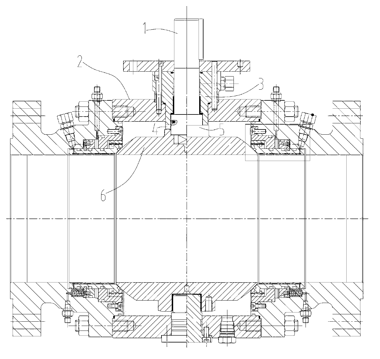
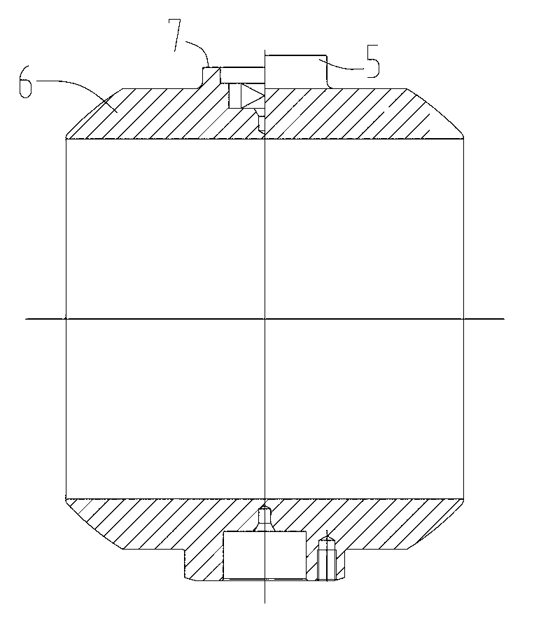
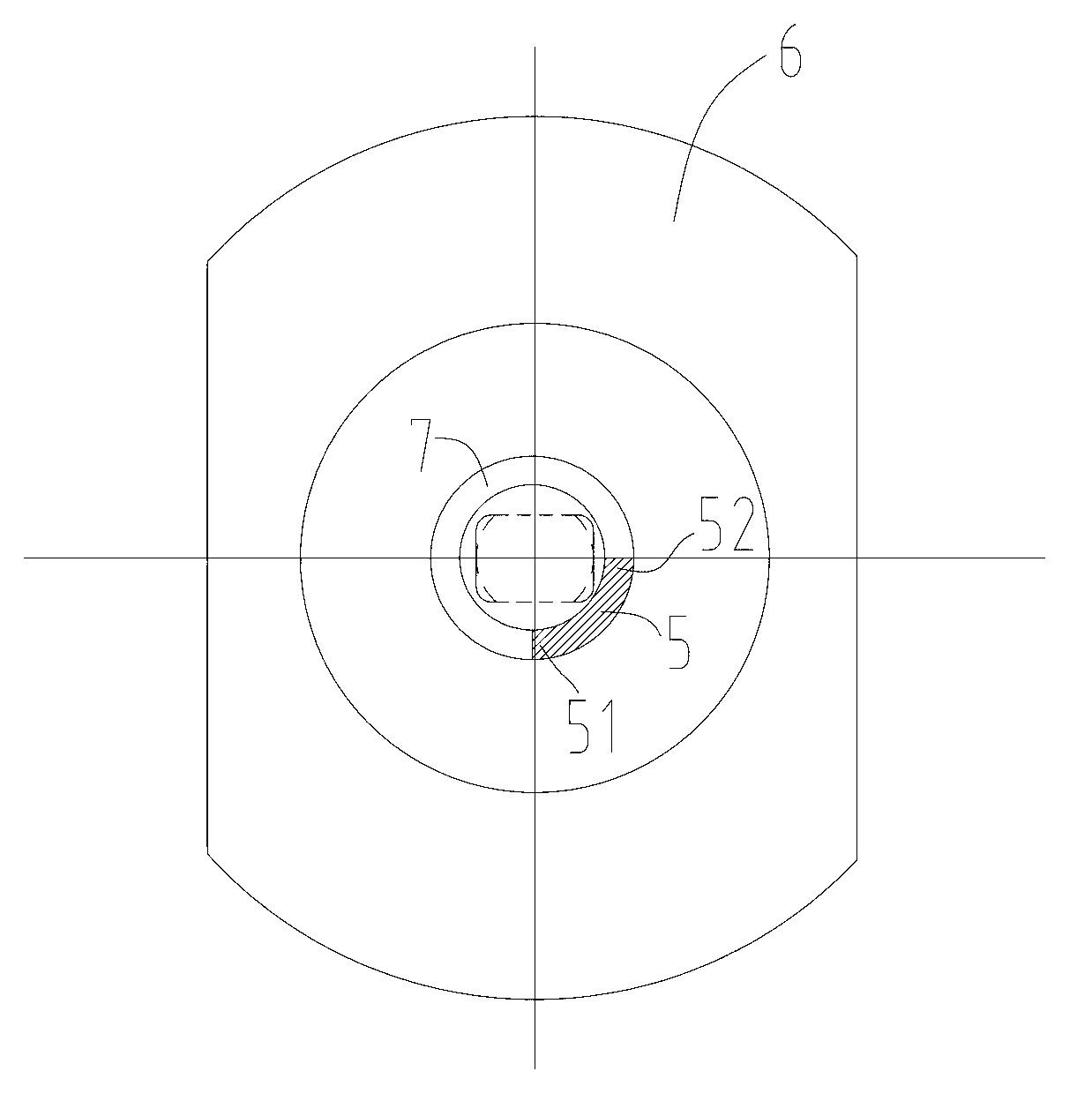
[0016] Such as Figure 1 to Figure 6 As shown, the limit ball valve includes a valve body 2, a ball 6 located in the valve body and a valve stem 1 for driving the ball to rotate. The valve stem 1 is arranged in a sealing ring 3 fixedly connected with the valve body. A stem connection hole 7 is arranged on the end surface of the sphere, and the valve stem 1 is connected to the sphere 6 through the valve stem connection hole 7. The sphere is provided with two sphere limit structures, which are respectively the sphere opening limit structure 51 and the sphere closing limit structure. Positioning structure 52; the valve body 2 is provided with an opening positioning structure 81 and a closing positioning structure 82 fixedly connected with the valve body 2 along the rotation direction of the ball 6 and corresponding to the two ball limiting structu...


PUM


Abstract

The invention discloses a limiting ball valve capable of being accurately opened and closed. The limiting ball valve comprises a valve body, a ball body and a valve rod, wherein the ball body is positioned in the valve body; the valve rod is used for driving the ball body to rotate, and the valve rod is arranged in a sealing ferrule fixedly connected with the valve body; the end surface of the ball body is provided with a valve rod connecting hole; the valve rod is connected with the ball body through the valve rod connecting hole; the ball body is provided with two ball body limiting structures which respectively include a ball body opening limiting structure and a ball body closing limiting structure; and an opening positioning structure and a closing positioning structure which are fixedly connected with the valve body and are in one-to-one correspondence to the two ball body limiting structures along the rotating direction of the ball body are arranged in the valve body. The limiting ball valve disclosed by the invention can be ensured to be accurately opened and closed no matter how the volume of the ball body to be changed because the limiting ball valve is not influenced by the volume size of the ball body. Thus, when the limiting ball valve is designed, the diameter of the ball body can reach minimum, and required input torque is reduced, therefore the manufacturing cost is reduced.

Description

technical field [0001] The invention relates to a ball valve, in particular to a limit ball valve. Background technique [0002] In the prior art, the torque force required for the rotation of the ball comes from the torsion force acting on the valve stem, and the rotation is realized through the key or square head on the valve stem and the keyway or square hole on the ball. And due to the assembly of the ball valve, whether it is a key connection or a square head connection, there will be an assembly gap and a design gap at all positions. Due to the existence of this gap, the conventionally designed limit device is installed outside the valve body, such as: the connection plate There are one or two symmetrical crescent ring grooves and the key on the valve stem to form the positioning of the ball valve switch position. Due to the existence of the assembly gap and the design gap, when the valve stem is turned, there will be a rotation angle difference between the ball and t...

Claims


Application Information

Patent Timeline
IPC IPC(8): F16K5/06F16K5/08
Inventor 顾立东其他发明人请求不公开姓名
Owner SICHUAN KCON VALVE MFG
Why Eureka
Try Eureka