Image encoding method, image decoding method, image encoding device, image decoding device, and image encoding/decoding device
An image encoding and image decoding technology, which is applied in image communication, code conversion, television and other directions, and can solve the problems of image decoding influence and processing delay.
- Summary
- Abstract
- Description
- Claims
- Application Information
AI Technical Summary
Problems solved by technology
Method used
Image

Examples
Embodiment approach 1
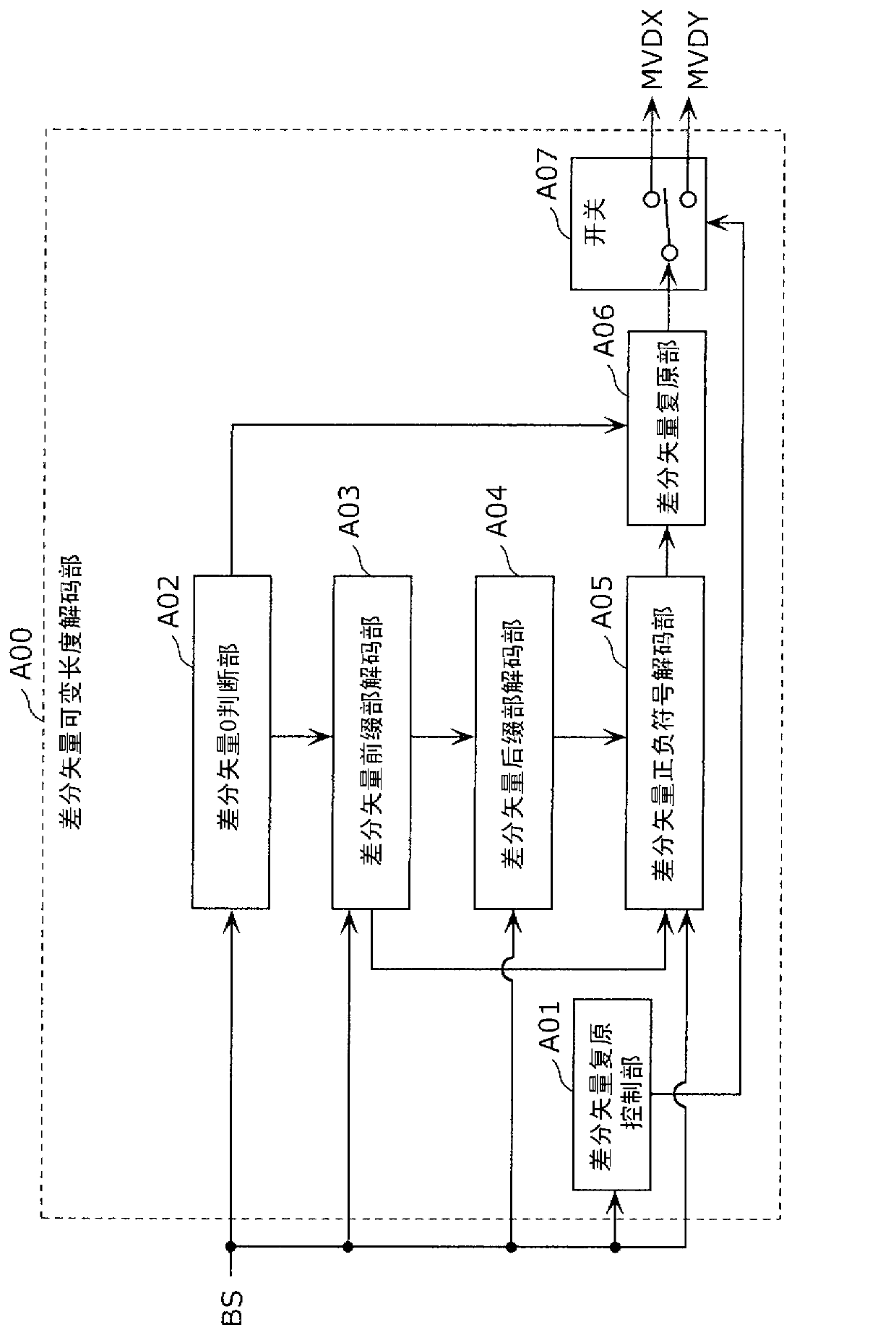
[0128] Figure 7 It is a block diagram showing the functional configuration of the difference vector decoding unit 100 according to the first embodiment.
[0129] The difference vector decoding unit 100 according to this embodiment is composed of a prefix part decoding unit 110 , a suffix part decoding unit 120 , a difference vector restoration control unit 101 , and a difference vector restoration unit 106 . Among them, the prefix portion decoding unit 110 is composed of a difference vector 0 determination unit 102 and a difference vector prefix portion decoding unit 103 . Furthermore, the suffix part decoding unit 120 is composed of the difference vector suffix part decoding unit 104 and the difference vector sign decoding unit 105 . Then, the difference vector decoding unit 100 restores the information of the X component MVDX and the Y component MVDY of the difference vector from the bit stream BS.
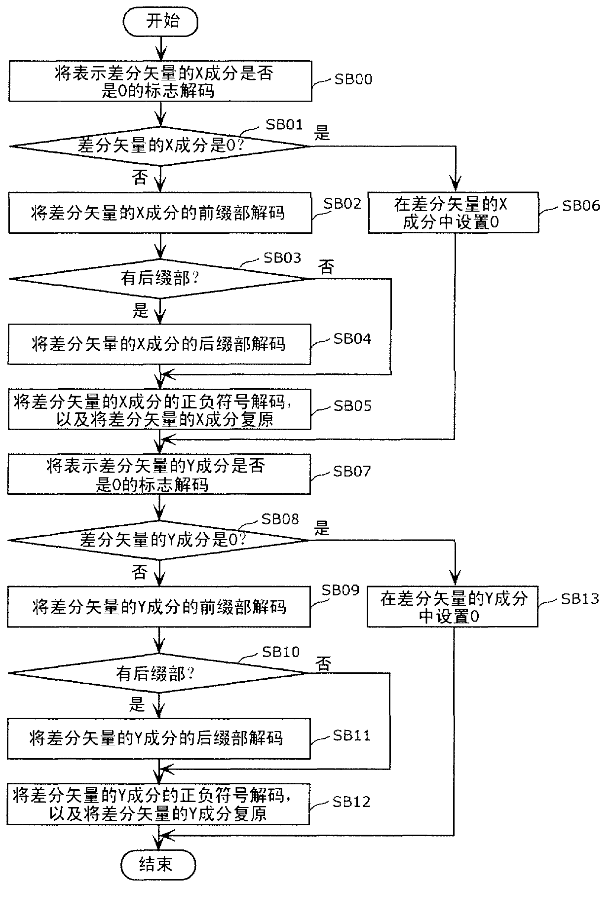
[0130] use Figure 8 The operation of the difference vector decoding un...
Embodiment approach 2
[0170] The outline of the arithmetic coding method of this embodiment will be described. The arithmetic coding method of this embodiment is characterized in that the difference vector is not divided into X components and Y components, but divided into a prefix part corresponding to context-adaptive arithmetic coding and a suffix part corresponding to bypass processing coding. Thereby, parallelization of processing is realized, and high-speed encoding is realized.
[0171] The above is the description of the outline of the arithmetic coding method of this embodiment. Unless otherwise specified, it means that the same method as the conventional arithmetic coding method can be adopted.
[0172] Next, a description will be given of the flow of processing of the differential vector encoding unit that performs the differential vector encoding method of the present embodiment.
[0173] Figure 12 It is a flowchart showing the flow of processing of the difference vector encoding un...
Embodiment approach 3
[0201] In this embodiment, the characteristic structure and procedure included in Embodiment 1 or Embodiment 2 are shown suggestively. The structure and procedure of this embodiment correspond to the structure and procedure shown in Embodiment 1 or Embodiment 2. That is, the concept shown in Embodiment 1 and Embodiment 2 includes the structure and procedure related to this embodiment.
[0202] Figure 15A It is a block diagram showing an example of the configuration of the image encoding device according to the present embodiment. Figure 15A The illustrated image encoding device 800 encodes an image using motion vectors. Furthermore, the image encoding device 800 includes an encoding unit 801 .
[0203] Figure 15B yes means Figure 15A The flow chart of the processing operation of the image encoding device 800 is shown. The encoding unit 801 encodes the difference vector ( S801 ). The difference vector represents the difference between the predicted motion vector and ...
PUM
 Abstract
Description
Claims
Application Information
 - R&D
- Intellectual Property
- Life Sciences
- Materials
- Tech Scout
- Unparalleled Data Quality
- Higher Quality Content
- 60% Fewer Hallucinations
Browse by: Latest US Patents, China's latest patents, Technical Efficacy Thesaurus, Application Domain, Technology Topic, Popular Technical Reports.
© 2025 PatSnap. All rights reserved.Legal|Privacy policy|Modern Slavery Act Transparency Statement|Sitemap|About US| Contact US: help@patsnap.com