Automatic stator blade distance adjusting device for vertical roller mill powder concentrator

An automatic adjustment, powder separator technology, applied in the direction of solid separation, separation of solids from solids with air flow, grain processing, etc., can solve the problem of reducing the adaptability of vertical mills to grinding materials, and the adjustment of the distance between static blades is manual Phases, reducing the operating rate of vertical mill equipment, etc., to achieve the effect of ensuring continuous and stable operation, improving equipment operating rate, and low manufacturing and maintenance costs

Active Publication Date: 2014-07-30
中材(天津)粉体技术装备有限公司 +1
View PDF6 Cites 0 Cited by
  • Summary
  • Abstract
  • Description
  • Claims
  • Application Information

AI Technical Summary

Problems solved by technology

At present, the spacing of the stationary blades of some mills is fixed and cannot be adjusted, which greatly reduces the adaptability of the vertical mill to the grinding materials.
The static blades of some powder classifiers can be adjusted, but it can only be completed by the operator after the vertical mill system is shut down, that is, the adjustment of the spacing of the static blades is still in the manual stage.
Manually adjusting the spacing of the stator blades seriously affects the automation of the vertical mill, and greatly reduces the equipment operation rate of the vertical mill

Method used


Image

  • Automatic stator blade distance adjusting device for vertical roller mill powder concentrator
  • Automatic stator blade distance adjusting device for vertical roller mill powder concentrator
  • Automatic stator blade distance adjusting device for vertical roller mill powder concentrator

Examples


Embodiment Construction

[0012] In order to further understand the invention content, characteristics and effects of the present invention, the following examples are given, and detailed descriptions are as follows in conjunction with the accompanying drawings:

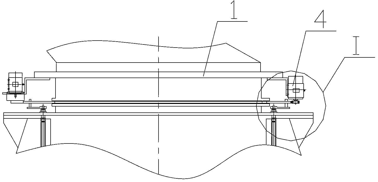
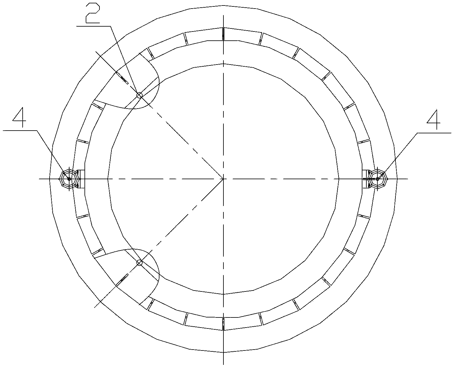
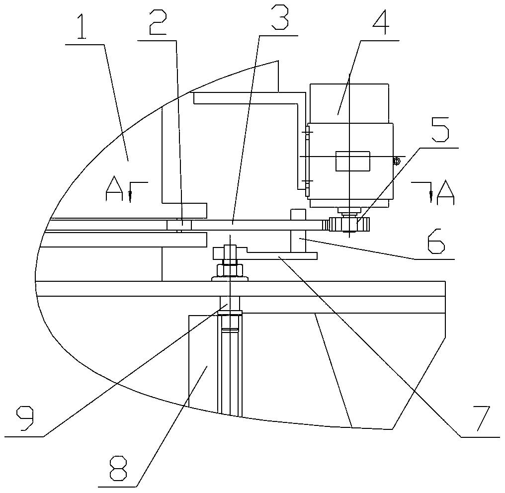
[0013] See Figure 1 to Figure 4 , an automatic adjustment device for the spacing between stationary blades of a vertical roller mill powder separator, comprising an annular drive disk 3 horizontally arranged at the center of the powder separator housing, and the annular drive disk 3 is provided with a stationary blade 8 of the powder separator. The number of equal and evenly arranged outer notch grooves 10, each of the outer notch grooves 10 is inserted with a pin shaft 6, and the pin shaft 6 is vertically fixed on the horizontal rocker arm 7, and the horizontal rocker arm 7 is connected to the vertical rocker arm 7. The pivot 9 is affixed, and the vertical pivot 9 is affixed to the stationary blade 8 of the powder separator, and the vertica...


PUM


Abstract

The invention discloses an automatic stator blade distance adjusting device for a vertical roller mill powder concentrator. The automatic stator blade distance adjusting device comprises an annular driving disc which is horizontally arranged in the center of a powder concentrator shell, wherein outside notch grooves which have the equal number with the stator blades of the powder concentrator and are uniformly arranged are arranged on the annular driving disc; a pin shaft is inserted into each outside notch groove; the pin shaft is vertically and fixedly connected to a horizontal rocker arm; the horizontal rocker arm is fixedly connected with a vertical pivot; the vertical pivot is fixedly connected with the stator blades of the powder concentrator; the vertical pivot is rotationally connected with the powder concentrator shell; an inner ring of the annular driving disc is in friction connection with at least three guide wheels which are uniformly distributed; the guide wheels are arranged on the powder concentrator shell; an outer ring of the annular driving disc is meshed with two driving gears which are symmetrically arranged; each driving gear is provided with a driving mechanism; the driving mechanism is arranged on the powder concentrator shell; the pin shaft is a stepped shaft; and the annular driving disc is supported on a shaft shoulder of the pin shaft. According to the device, the stator blade distance can be automatically adjusted according different material grindabiliies and different finished product requirements.

Description

technical field [0001] The invention relates to a vertical roller mill powder separator, in particular to an automatic adjustment device for the distance between stationary blades of the vertical roller mill powder separator. Background technique [0002] The vertical mill integrates crushing, drying, grinding, and grading conveying in one, with high production efficiency, and can grind block, granular and powder raw materials into required powder materials. [0003] The vertical mill system includes the main transmission device, grinding disc device, lubrication device, hydraulic device, powder selection device, etc. The powder classifier classifies the pulverized materials brought up by the gas through the stationary blades of the powder classifier, and screens out the fine powder that meets the product fineness requirements. In order to meet the adaptability of the vertical mill to various materials and control the finished products with different fineness, the spacing o...

Claims


Application Information

Patent Timeline
Patent Type & Authority Patents(China)
IPC IPC(8): B02C23/20B07B11/00B07B7/083
Inventor 滑松赵剑波申占民彭凌云崔军利丁再珍
Owner 中材(天津)粉体技术装备有限公司
Why Eureka
Try Eureka