High-strength rolling mill

A high-strength, rolling mill technology, applied in the direction of metal rolling stands, metal rolling mill stands, metal rolling, etc., can solve the problems of easy loosening and difficulty in tightening the threaded pressure ring, preventing axial movement and preventing steel The effect of exceeding the tolerance and reducing the phenomenon of roll change

Active Publication Date: 2015-06-03
DAYE SPECIAL STEEL CO LTD
View PDF8 Cites 0 Cited by
  • Summary
  • Abstract
  • Description
  • Claims
  • Application Information

AI Technical Summary

Problems solved by technology

[0004] The object of the present invention is to provide a high-strength rolling mill (also known as a high-rigidity rolling mill) to solve the problem in the prior art that the threaded pressure ring for axial fixing of the roll is difficult to tighten and easy to loosen

Method used


Image

  • High-strength rolling mill
  • High-strength rolling mill
  • High-strength rolling mill

Examples


Embodiment Construction

[0025] The present invention will be described in further detail below in conjunction with the accompanying drawings and specific embodiments.

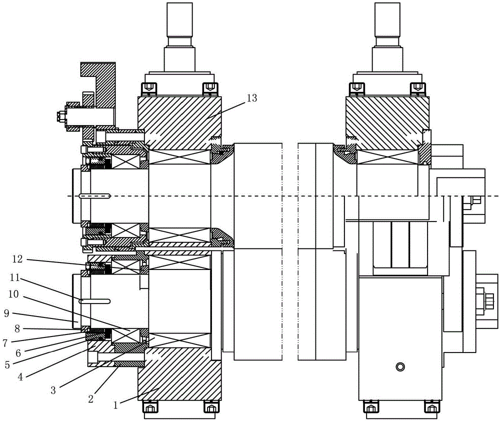
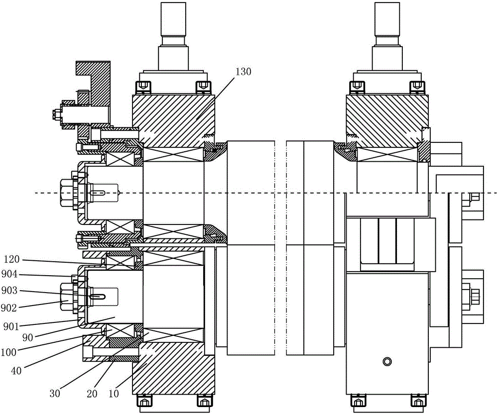
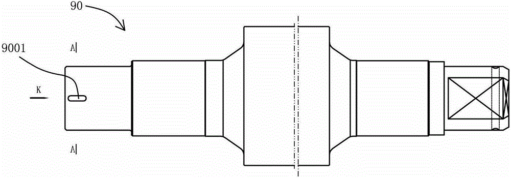
[0026] figure 2 Schematically shows the structure of the preferred embodiment of the present invention, as shown in the figure, this preferred embodiment includes a fixed end lower bearing seat 10, an inner end cover 20, an inner bearing 30, an outer end cover 40, an outer bearing 100, a fixed end The spacer ring 120, the upper bearing seat 130, the roll 90 and the shaft cover 901, bolts 902, keys 903 and screws 904 constitute the axial fixing system. Wherein, the inner bearing 30 and the outer bearing 100 are located at the end of the roll 90, the inner bearing 30 is installed on the bearing housing 10, the inner end cover 20 is fixed on the bearing housing 10, and the outer end cover 40 is fixed on the inner end cover 20, axially The fixing system is located in the annular space inside the outer end cover 40 to fix the fixed end o...


PUM


Abstract

The invention provides a high-strength rolling mill which comprises a roller, an inner bearing, an outer bearing, a bearing pedestal, an inner end cover, an outer end cover and an axial fixing system. The inner bearing and the outer bearing are located at the end part of the roller; the bearing pedestal is used for mounting the inner bearing; the inner end cover is fixed with the bearing pedestal; the outer end cover is fixed with the inner end cover; the axial fixing system is fixed at the end part of the roller, located in an annular space in the outer end cover, and comprises a shaft end cover, keys, and a fixing structure; the shaft end cover comprises a side wall and a baseplate, the side wall is cylindrical, the baseplate is arranged at the outer end of the side wall, the end part of the roller is sleeved with the roller, the outer edge of the inner end of the side wall is provided with a convex edge extending around the side wall, and the inner surface of the convex edge is close to the inner bearing; the keys are arranged between the inner surface of the side wall and the side surface of the end part of the roller; the fixing structure is connected between the baseplate and the end surface of the end part of the roller and is used for fixing the shaft end cover to the end part of the roller; a first key slot is formed in the inner surface of the side wall; a second key slot is formed in the side surface of the fixed end of the roller; and the keys are arranged in the first key slot and the second key slot respectively. The high-strength rolling mill can prevent the roller from axial movement.

Description

technical field [0001] The invention relates to a high-strength rolling mill, in particular to an axial fixing system for a fixed end of the high-strength rolling mill. Background technique [0002] Rolling mill is the equipment to realize the metal rolling process, among which, high-strength rolling mill is widely used. High-strength rolling mills, such as SY-type high-rigidity rolling mills, are new types of short-stress-line rolling mills without archways, suitable for small and medium-sized rolling mill renovations, and also suitable for small continuous rolling and semi-continuous rolling workshops. The fixed end structure of one of the rolls 9 of the current high-strength rolling mill is as follows: figure 1 as shown, figure 1 In , the meanings of reference signs are: 1 is the lower bearing seat; 2 is the inner end cover; 3 is the bearing; 4 is the end cover; 5 is the nut; 6 is the first spacer ring; 7 is the threaded pressure ring; 8 Thrust half ring; 9 is a roll; ...

Claims


Application Information

Patent Timeline
Patent Type & Authority Patents(China)
IPC IPC(8): B21B31/02
Inventor 徐政新
Owner DAYE SPECIAL STEEL CO LTD
Why Eureka
Try Eureka