Spinning unit and spinning machine

A spinning unit and spinning technology, applied to spinning machines, open-end spinning machines, continuous winding spinning machines, etc., can solve malfunctions, changes in spinning characteristics, malfunctions of air actuators, etc. problems, to achieve the effect of easy maintenance and preventing positional misalignment

Active Publication Date: 2013-04-03
MURATA MASCH LTD
View PDF2 Cites 3 Cited by
  • Summary
  • Abstract
  • Description
  • Claims
  • Application Information

AI Technical Summary

Problems solved by technology

[0006] However, in the spinning unit that uses the air actuator to move the spinning section, the characteristics of the spinning may change due to malfunction of the air actuator (shrinkage failure due to air leakage, etc.)
Specifically,

Method used


Image

  • Spinning unit and spinning machine
  • Spinning unit and spinning machine
  • Spinning unit and spinning machine

Examples


Example Embodiment

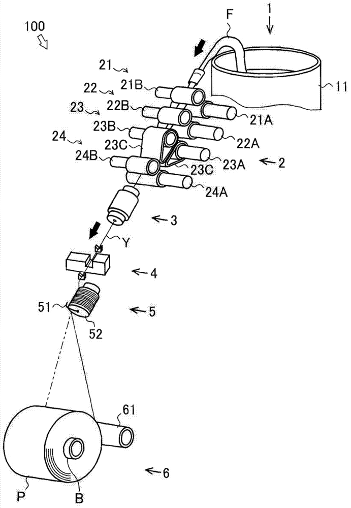
[0036] First, the overall structure of the spinning unit 100 will be briefly described. figure 1 The illustrated black arrow indicates the conveying direction of the fiber bundle F and the spun yarn Y. The spinning unit 100 is a spinning machine that manufactures spun yarn Y from the fiber bundle F to form a package P. The spinning unit 100 includes a sliver supply unit 1, a drafting unit 2, a spinning unit 3, a yarn defect detecting unit 4, a tension stabilizing unit 5, and a winding unit 6 along the conveying direction of the fiber bundle F and the spun yarn Y.

[0037] The sliver supply unit 1 supplies the fiber bundle F (sliver) to the drafting unit 2. The sliver supply unit 1 includes a sliver box 11 and a sliver guide (not shown). The fiber bundle F stored in the sliver box 11 is guided by the sliver frame and guided to the drafting unit 2.

[0038] The drafting unit 2 drafts the fiber bundle F to make the thickness of the fiber bundle F uniform. The drafting unit 2 includ...


PUM


Abstract

A spinning unit includes a drafting section (2) adapted to draft a fiber bundle (F), a spinning section (3) adapted to twist the fiber bundle (F) drafted by the drafting section (2), a pneumatic actuator (38) adapted to move the spinning section (3) in a direction away from the drafting section (2), and an elastic member (39) adapted to move the spinning section (3) in a direction towards the drafting section (2).

Description

technical field [0001] The present invention relates to the technology of spinning unit and spinning machine. Background technique [0002] Conventionally, a spinning unit is known that produces a spun yarn by drafting a fiber bundle and twisting the drafted fiber bundle (see, for example, JP-A-2011-99192). Such a spinning unit is provided with a drafting section that drafts a fiber bundle and a spinning section that twists the drafted fiber bundle. [0003] The draft section includes a plurality of draft roller pairs. The draft roller pair is composed of a bottom roller rotated by a power mechanism and a top roller driven to rotate while in contact with the bottom roller. Since the drafting roller pair rotates while the fiber bundle is held by the bottom roller and the top roller, the fiber bundle can be sent out. The drafting unit can draft the fiber bundle by the difference in delivery speed between the draft rollers adjacent to each other. [0004] The spinning secti...

Claims


Application Information

Patent Timeline
IPC IPC(8): D01H1/115D01H4/02
CPCD01H1/14
Inventor 坂元直孝丰田贵大
Owner MURATA MASCH LTD
Why Eureka
Try Eureka