
Indoor automatic pressurizing water storage box

A technology of automatic pressurization and water storage tank, applied in the direction of water saving, water supply device, configuration of water supply pool, etc., can solve the problems of water pollution, unsanitary, inconvenient water change in the water tank, save space and unique shape , the effect of simple structure

Active Publication Date: 2014-05-21
郑宜辉
View PDF7 Cites 0 Cited by
  • Summary
  • Abstract
  • Description
  • Claims
  • Application Information

AI Technical Summary

Problems solved by technology

[0003] In order to prevent water cut-off and water cut-off, some communities or households install water tanks on the roof, and the water in the water tanks is polluted from time to time, and the water in one water tank cannot meet the water needs of many users, and the water pressure is also unstable or very small
Some users have these problems in order to prevent water cut-off and water cut-off, especially when preparing tanks and buckets to hold water at home. Water often makes users who wait for water not sleep well; second, it is very inconvenient for users who are used to using the faucet to scoop water from tanks and buckets; The stored water will be stored for a few days, which will cause the water quality to deteriorate and become unhygienic. To prevent this from happening, it is necessary to change the water frequently. Not only is it inconvenient to change the water, but it also causes waste

Method used


Image

  • Indoor automatic pressurizing water storage box
  • Indoor automatic pressurizing water storage box
  • Indoor automatic pressurizing water storage box

Examples


Embodiment Construction

[0018] In order to describe the technical content, structural features, achieved goals and effects of the present invention in detail, the following will be described in detail in conjunction with the embodiments and accompanying drawings.

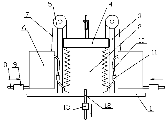
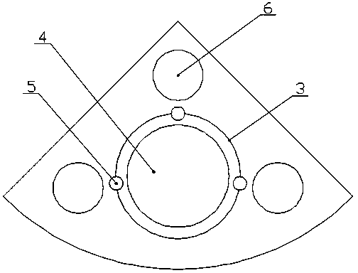
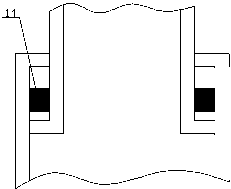
[0019] Referring to illustrations 1 to 3, an indoor automatic pressurized water storage tank includes a bottom plate 1, a closed container 2 with a variable volume is arranged in the middle of the bottom plate 1, and a bottom plate located on the periphery of the closed container 2 is provided for controlling the deformation of the closed container 2. Guardrail 3, the top of the airtight container 2 is provided with a briquetting block 4, the top of the guardrail 3 is provided with at least one fixed pulley 5, and the outer side of the guardrail 3 is provided with at least one pressure regulating water storage bucket 6, and the pressure regulating water storage bucket 6 is filled with filter material for purifying water quality, the upper e...


PUM


Abstract

The invention discloses an indoor automatic pressurizing water storage box. The indoor automatic pressurizing water storage box comprises a bottom plate, wherein a sealed container with variable volume is arranged in the middle of the bottom plate; a press block is arranged above the sealed container; a fixed pulley is arranged at the top end of a guardrail; a pressure regulating water storage bucket is arranged on the external side of the guardrail; a filtering material for purifying water quality is filled in the pressure regulating water storage bucket; the upper end part of the pressure regulating water storage bucket is connected with one end part of a rope; the other end part of the rope is connected with the press block after being wound on the fixed pulley; the bottom of the pressure regulating water storage bucket is connected with a water inlet pipe; a water inlet control valve is arranged on the water inlet pipe; the upper end part of the pressure regulating water storage bucket is connected with a water inlet in the bottom of the sealed container; and a one-way water inlet valve is arranged on a hose. The indoor automatic pressurizing water storage box disclosed by the invention has the advantages of simple structure and reasonable design and has functions of automatically replacing, supplementing and storing water in the water tank; and moreover, the water coming out from the water tank can be automatically pressurized so as to satisfy requirements on temporary water usage of people.

Description

technical field [0001] The invention relates to industrial or civil water storage equipment, in particular to an indoor automatic pressurized water storage tank. Background technique [0002] In areas where tap water supply is unstable or regular water supply, residents may experience water cut-offs and cut-offs when using water. Water cutoffs often occur during the peak period of water use, especially for high-rise residents in high-rise buildings. [0003] In order to prevent water cut-off and water cut-off, some communities or households install water tanks on the roof, and the water in the water tanks is polluted from time to time, and the water in one water tank cannot meet the water needs of many users, and the water pressure is also unstable or very small. Some users have these problems in order to prevent water cut-off and water cut-off, especially when preparing tanks and buckets to hold water at home. Water often makes users who wait for water not sleep well; se...

Claims


Application Information

Patent Timeline
Patent Type & Authority Patents(China)
IPC IPC(8): E03B11/02
CPCY02A20/00
Inventor 郑宜辉
Owner 郑宜辉
Learn More