

Sintering control method and system
A technology of sintering control and sintering end point, which is applied in the field of sintering, can solve the problems of energy waste of the main exhaust fan, etc., and achieve the effects of avoiding mass production, stabilizing the speed of the trolley, and reducing waste
- Summary
- Abstract
- Description
- Claims
- Application Information
AI Technical Summary
Problems solved by technology
Method used
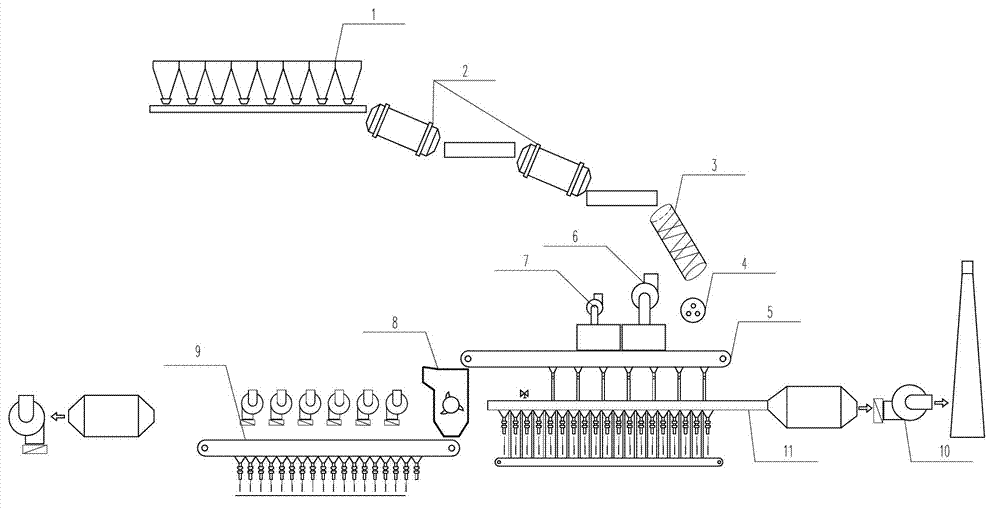
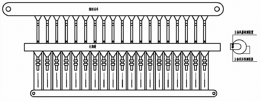
Image

Examples
Embodiment 1
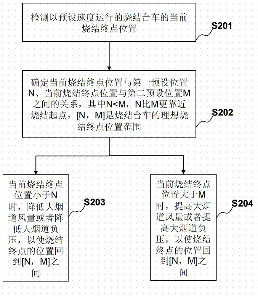
[0042] figure 2 It is a flow chart of Embodiment 1 of the sintering control method of the present application, and the method includes:
[0043] S201. Detect the current sintering end position of the sintering trolley running at a preset speed.
[0044] In some embodiments of the present invention, the running speed of the sintering trolley can be determined according to the sintering output. After the required sintering output is determined, the running speed of the sintering trolley and the height of the material layer can be further determined according to the width of the trolley. In the present invention, under normal circumstances (except when the output needs to be changed), the speed of the trolley is kept stable.
[0045] S202. Determine the relationship between the current sintering end position and the first preset position N, the current sintering end position and the second preset position M, wherein the first preset position N is smaller than the second preset ...
Embodiment 2
[0067] This embodiment is based on the first embodiment, and is a refinement made on the basis of the first embodiment, especially the further refinement of the steps of reducing the air volume of the large flue or reducing the negative pressure of the large flue when the current sintering end position is less than N.
[0068] In the method of this embodiment, when the current sintering end position is less than N, [0, N) is divided into n sub-intervals in advance, where 0 is the sintering starting point, and the mth sub-interval is [N m-1 , N m ), 1≤m≤n, and m, n are integers, N 0 =0,N n =N,01 2 ...n-1
[0069] The step of reducing the air volume of the large flue or reducing the negative pr...
Embodiment 3
[0075] This embodiment is based on Embodiment 1 and corresponds to Embodiment 2. It is a refinement made on the basis of Embodiment 1, especially for increasing the air volume of the large flue or increasing the load of the large flue when the current sintering end position is greater than M. Further refinement of the pressing steps.
[0076] In this embodiment, when the current sintering end position is greater than M, (M, W] is divided into p subintervals in advance, where W represents the end position of the sintering trolley, and the qth subinterval is (M q-1 ,M q ], 1≤q≤p, and q is an integer, M 0 = M, M p =W,M1 2 ...p-1
PUM
 Abstract
Description
Claims
Application Information