
Device and method for detecting optical-axis offset of lens in equipment

A technology of optical axis offset and detection equipment, applied in the field of optical detection, to achieve the effect of simple and easy detection

Active Publication Date: 2013-04-03
GOERTEK OPTICAL TECH CO LTD
View PDF8 Cites 67 Cited by
  • Summary
  • Abstract
  • Description
  • Claims
  • Application Information

AI Technical Summary

Problems solved by technology

[0004] The invention provides a device and method for detecting the optical axis deviation of the lens in the equipment, so as to solve the problem that the optical axis deviation of the lens in the equipment cannot be detected during the assembly process

Method used


Image

  • Device and method for detecting optical-axis offset of lens in equipment
  • Device and method for detecting optical-axis offset of lens in equipment
  • Device and method for detecting optical-axis offset of lens in equipment

Examples


Embodiment Construction

[0045] In order to make the object, technical solution and advantages of the present invention clearer, the implementation manner of the present invention will be further described in detail below in conjunction with the accompanying drawings.

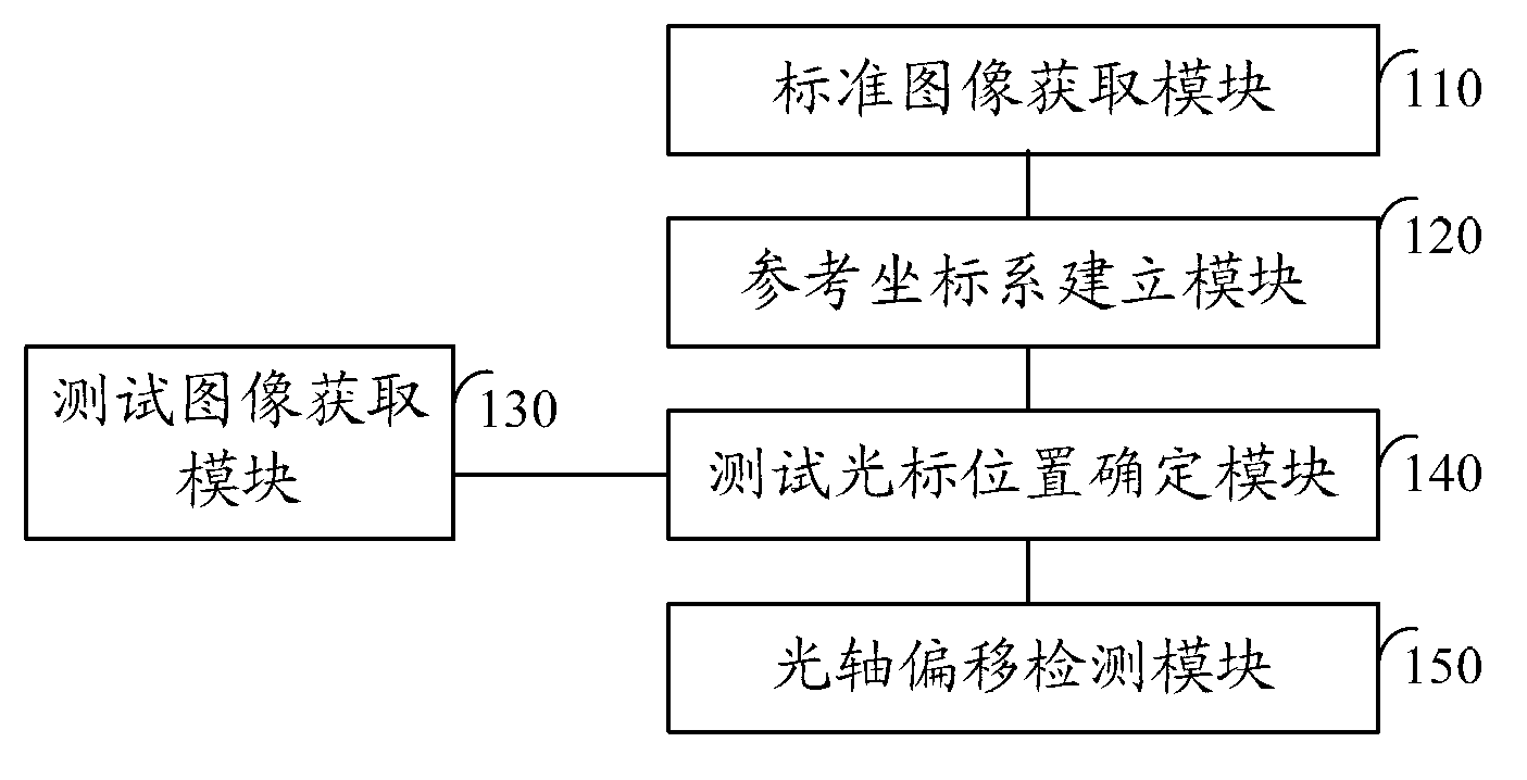
[0046] see figure 1 , is a structural diagram of the device for detecting the optical axis deviation of the lens in the device in an embodiment provided by the present invention. The device includes: a standard image acquisition module 110 , a reference coordinate system establishment module 120 , a test image acquisition module 130 , a test cursor position determination module 140 and an optical axis offset detection module 150 .

[0047] The standard image acquiring module 110 is configured to take a picture sample after focusing the standard lens assembled in the device at the shooting position, and obtain a standard image of the picture sample.

[0048] Wherein, the standard lens is a lens whose determined optical axis offset is w...


PUM


Abstract

The invention discloses a device and a method for detecting optical-axis offset of a lens in equipment. The device comprises a standard image acquiring module, a reference coordinate system setup module, a test image acquiring module, a test cursor position determining module and an optical-axis offset detecting module, wherein the standard image acquiring module is used for focusing a standard lens assembled in the equipment at a pickup position, picking up an image sample and acquiring a standard image of the image sample; the reference coordinate system setup module is used for taking the center of the standard image as coordinate origin and setting up a reference coordinate system; the test image acquiring module is used for focusing a to-be-detected lens assembled in the equipment at the pickup position, picking up the image sample and acquiring a test image of the image sample; the test cursor position determining module is used for taking the center of the test image as test cursor and determining the position of the test cursor in the reference coordinate system; and the optical-axis offset detecting module is used for determining optical-axis offset and / or optical-axis offset angle of the to-be-detected lens according the position. The device and the method for detecting optical-axis offset of the lens can solve the technical problem that the optical-axis offset of the lens in the equipment cannot be detected during assembly.

Description

technical field [0001] The invention relates to the field of optical detection, in particular to a device and a method for detecting the optical axis deviation of a lens in a device. Background technique [0002] In the prior art, for a device with a lens, the lens in the device may have an optical axis deviation due to a defect of the lens itself or an operation problem during assembly. [0003] The optical axis offset detection in the prior art is a static detection, and can only be realized with detailed design parameters of the lens and expensive testing equipment. When the lens is assembled on the printed circuit board PCBA, after the focusing process, the optical axis shift cannot be determined. However, due to assembly tolerances, optical sensor patch tolerances, lens positioning, etc., the lens in the device after assembly will have an optical axis offset. If the optical axis offset exceeds the allowable tolerance range, it will cause uneven brightness of the lens,...

Claims


Application Information

Patent Timeline
IPC IPC(8): G01M11/02
CPCG01B11/27G01B11/272G01M11/0221
Inventor 曲明东张坤张雄唐云学
Owner GOERTEK OPTICAL TECH CO LTD
Learn More