Three-dimensional (3D) display device and driving method thereof

A technology of a display device and a driving method, applied in the field of 3D display, can solve problems such as 3D crosstalk of lens gratings, and achieve the effect of improving the problem of image crosstalk and improving the 3D display effect.

Inactive Publication Date: 2013-04-03
BOE TECH GRP CO LTD
View PDF7 Cites 12 Cited by
  • Summary
  • Abstract
  • Description
  • Claims
  • Application Information

AI Technical Summary

Problems solved by technology

[0007] Embodiments of the present invention provide a 3D display device and a dri...

Method used


Image

  • Three-dimensional (3D) display device and driving method thereof
  • Three-dimensional (3D) display device and driving method thereof
  • Three-dimensional (3D) display device and driving method thereof

Examples


Embodiment 1

[0045] Embodiment 1: from Figure 7a The first frame shown to the Figure 7b In the process of the second frame picture shown, the change of each lens unit of the liquid crystal lens is taken as an example to illustrate the above driving method.

[0046] At the first moment when the second frame starts to scan, such as Figure 9a As shown, the sub-pixel unit in the first column on the left side of the display panel changes from the image for the left eye (the image for the left eye is indicated by a thin line inclined to the left) to the image for the right eye of the second frame (the image for the right eye is indicated by a line inclined to the right) Indicated by the thin line of ), the lens structure of the area A in the corresponding lens unit is reconstructed and becomes a lens structure that matches the image for the right eye, the lens structure of other areas in the lens unit remains unchanged, and other The lens unit is also unchanged.

[0047] At the second mome...

Embodiment 2

[0052] Embodiment two: from Figure 7a The first frame shown to the Figure 7b The black frame image is inserted in the process of the second frame picture shown, and the changes of each lens unit in the liquid crystal lens are as follows:

[0053] At the first moment when the black frame image starts to scan, such as Figure 11a As shown in , when the sub-pixel unit in the first column on the left of the display panel changes from the image for the left eye (the image for the left eye is indicated by a thin line inclined to the left) to a black frame image (the image for the left eye is indicated by a horizontal line), the corresponding The lens structure of area A in the lens unit is reconstructed and becomes the lens structure that matches the right-eye image to be displayed in the second frame. The lens structures of other areas in the lens unit remain unchanged, and other lens units also have no Variety.

[0054] At the second moment when the black frame image starts t...


PUM


Abstract

The invention discloses a three-dimensional (3D) display device and a driving method thereof. Each pixel unit on a display panel is rotated by 90 degrees, grid signal lines are arranged vertically and data signal lines are arranged horizontally, so that the display panel changes a line-by-line scan driving mode into a column-by-column scan driving mode. A liquid crystal lens positioned on the display panel has a plurality of lens units corresponding to adjacent at least two columns of subpixel units; in the 3D display mode, when each column of subpixel units in the display panel is refreshed, areas, corresponding to the column of subpixel units, in the corresponding lens units synchronously change the lens structure, so that the lens structure is matched with an image of a corresponding to-be-displayed view of the column of subpixel units; the image in two viewpoints is an image for a left eye or an image for a right eye; and the image displayed after the column of subpixel units is refreshed can enter a proper visual area under the action of the refreshed liquid crystal lens, so that the problem of image crosstalk of the 3D display device is improved and the 3D display effect is improved.

Description

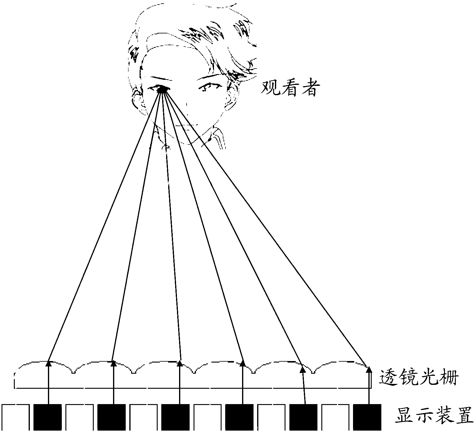
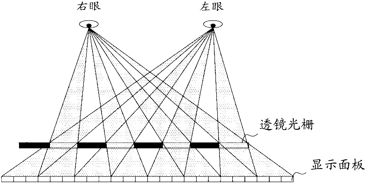
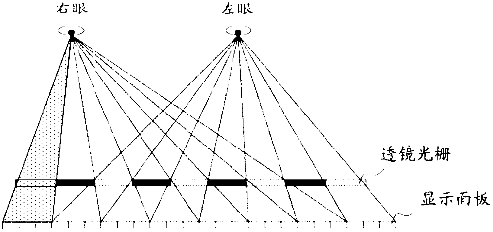
technical field [0001] The present invention relates to the technical field of 3D display, in particular to a 3D display device and a driving method thereof. Background technique [0002] With the development of science and technology, three-dimensional (3D) stereoscopic display, especially naked-eye 3D stereoscopic display technology has become one of the inevitable trends in the display field. At present, the mainstream glasses-free 3D technology is mainly divided into two types: parallax barrier type and lenticular grating type. The principles of the parallax barrier type and the lens grating type are very similar. Taking the lens grating type as an example, the schematic diagram of the principle is as follows figure 1 As shown, the lens grating is used to form several viewing areas in front of the display panel, so that the light emitted by different sub-pixel units on the display panel falls in different viewing fields, and the eyes of the viewer fall in different view...

Claims


Application Information

Patent Timeline
IPC IPC(8): G02F1/29G02F1/133G02B27/22G02B30/28
CPCH04N13/398H04N13/305G02B30/28G02B30/27
Inventor 武延兵
Owner BOE TECH GRP CO LTD
Why Eureka
Try Eureka