Dial assembly and timepiece

A technology for assembling bodies and dials, which is applied to clocks, mechanically driven clocks, and time-indicating mechanical devices, and can solve problems such as shortening the hour or minute hands and unsightly clocks

Inactive Publication Date: 2013-04-03
SEIKO EPSON CORP
View PDF7 Cites 15 Cited by
  • Summary
  • Abstract
  • Description
  • Claims
  • Application Information

AI Technical Summary

Problems solved by technology

[0003] However, in the timepiece described in Patent Document 1, due to the thickness of the display part, that is, the amount of protrusion of the display part from the surface on the front side of the dial, the display part may in

Method used


Image

  • Dial assembly and timepiece
  • Dial assembly and timepiece
  • Dial assembly and timepiece

Examples


Embodiment Construction

[0034] Next, the dial assembly and the timepiece of the present invention will be described in detail based on preferred embodiments shown in the drawings.

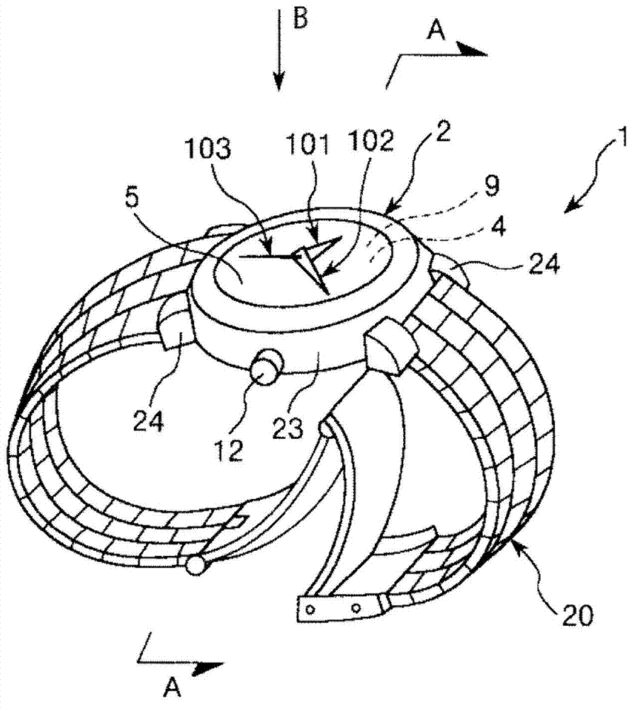
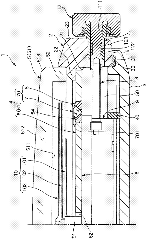
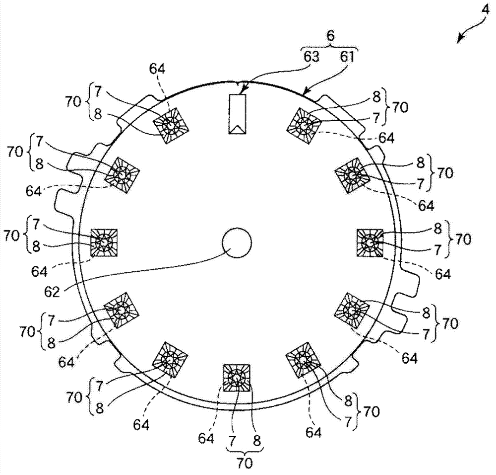
[0035] figure 1 It is a perspective view showing an embodiment when the timepiece of the present invention having the dial assembly of the present invention is applied to a wristwatch, figure 2 yes figure 1 The A-A line sectional view in, image 3 It is viewed from the direction of arrow B figure 1 Diagram of the dial assembly in (top view), Figure 4 yes figure 1 A perspective view of a decorative structure in the clock shown, Figure 5 to Figure 9 Each is a cross-sectional view sequentially showing the steps of assembling the dial assembly of the present invention. In addition, for the convenience of explanation below, the figure 1 , figure 2 as well as Figure 4 ~ Figure 9 The upper side is called "upper", "upper" or "front", and the lower side is called "lower", "lower" or "back".

[0036] figure 1 , fi...


PUM


Abstract

To provide a dial assembly, for which it is possible to suppress the projection of the decorative member from the front side surface of the dial, and a timepiece, a dial assembly (4) is held inside a timepiece (1) together with a movement which supports an hour hand (101) and a minute hand (102) to be able to rotate. This dial assembly (4) is equipped with a plate shaped dial (6), and at least one decorative structure (70) having a decorative member that can be visually recognized from the front side of the dial, and a support member for supporting the decorative member on the dial. Also, the dial (6) has a fixing part (64) for fixing the decorative structure, which is constituted with through holes piercing the dial (6) in the thickness direction. Then, the decorative structure (70) is fixed by being inserted in the fixing part (64) from the back side of the dial (6) in a state with the decorative member (7) and the support member (8) assembled.

Description

technical field [0001] The present invention relates to a dial assembly and a timepiece. Background technique [0002] Among the conventional wristwatches, it is known that some wristwatches have a dial and a plate-shaped display part, wherein a plurality of said display parts are arranged on the surface on the front side of the dial, and these display parts respectively correspond to Numerals from 1 to 12 representing time (for example, refer to Patent Document 1). In the timepiece described in Patent Document 1, rod-shaped legs are integrally protrudingly formed on the back surface of the display member. On the other hand, mounting holes for inserting the legs are formed on the dial at positions where the respective display components are respectively arranged. Then, each display member is fixed by inserting the leg portion of each display member into the mounting hole from the front side of the dial, and crimping the inserted leg portion from the back side of the dial f...

Claims


Application Information

Patent Timeline
IPC IPC(8): G04B19/10
CPCG04B19/10G04B47/042
Inventor 大盐匠
Owner SEIKO EPSON CORP
Why Eureka
Try Eureka