Locking device and automatic cash transaction device

A technology for automatic transaction devices and lock devices, which is applied to devices for accepting coins, handling coins or valuable banknotes, instruments, etc., can solve problems such as difficult key rotation operations, and achieve the effect of improving operability

Inactive Publication Date: 2013-04-03
OKI ELECTRIC IND CO LTD
View PDF3 Cites 6 Cited by
  • Summary
  • Abstract
  • Description
  • Claims
  • Application Information

AI Technical Summary

Problems solved by technology

[0014] Therefore, there is the following problem in the automatic teller machine: when the key is inserted into the key hole of the lock 104 in the state where the cassette storage unit 100 is drawn out, the hand holding the key is not connected to one side surface 100A of the cassette storage unit 100 . contact, making it difficult to turn the key

Method used


Image

  • Locking device and automatic cash transaction device
  • Locking device and automatic cash transaction device
  • Locking device and automatic cash transaction device

Examples


no. 2 Embodiment approach

[0060] (3) Other implementations

[0061] (1) The first embodiment

[0062] (1-1) Appearance and structure of cash ATM

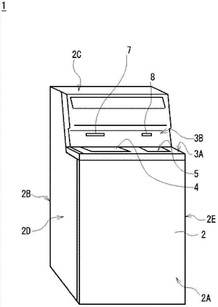
[0063] exist figure 1 In , reference numeral 1 represents the appearance structure of the cash automatic teller machine to which the present invention is applied as a whole. The cash automatic teller machine 1 has a substantially box-shaped housing (hereinafter, referred to as a cash machine housing) 2 .

[0064] A front panel 3 is provided on the front side upper end of the deposit and teller housing 2, and the front panel 3 is formed in a substantially L-shaped manner that is recessed toward the rear surface 2B side than the front surface 2A of the deposit and teller housing 2. shape.

[0065] In addition, in the following description, the front surface 2A of the deposit and withdrawal machine housing 2 is referred to as the deposit and withdrawal machine front surface 2A, and the rear surface 2B of the deposit and withdrawal machine housing 2 is refer...

Embodiment approach 1

[0339] In addition, in the above-mentioned first and second embodiments, for example, the case where the lock is switched by hooking a finger on one end of the lock 40 and pulling it to the left or pushing it to the right has been described. 40 poses.

[0340] However, the present invention is not limited thereto, and may also be Figure 16A and Figure 16B As shown, a protruding finger hook portion 71AX is provided on one surface of the top plate portion 71A of the lock mounting plate 71 of the lock holding portion 70, for example, at a position to the left of the end portion in the front direction. Figure 16A and Figure 16B in, right with Figure 7A and Figure 7B Corresponding parts are marked with the same reference numerals.

[0341] According to the present invention, according to the relevant structure, the lock mounting plate 71 can be pulled to the left or pushed to the right to switch the posture of the lock 40 by hooking the finger on the finger hook portion ...

Embodiment approach 2

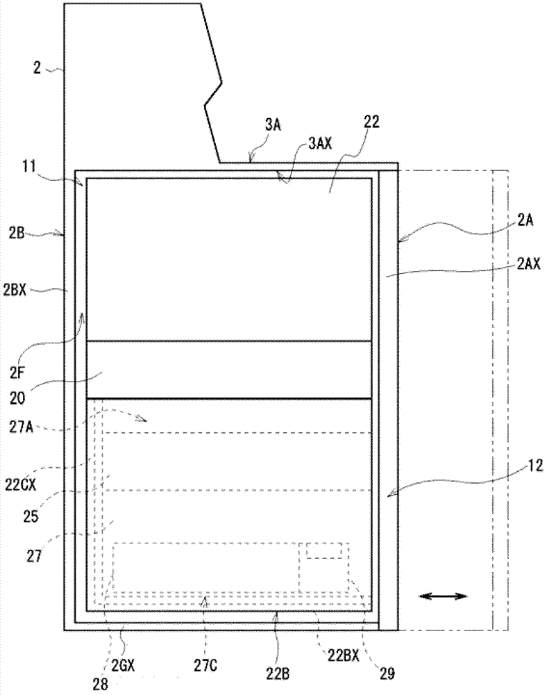
[0348] In addition, in the above-mentioned first embodiment, for example, the case where the right side 47AX of the lock mounting plate 47 is brought into contact with the storage unit left side 27A and the lock 40 is set in a parallel posture has been described.

[0349] However, the present invention is not limited thereto. For example, an opening or a recess corresponding to the lock mounting plate 47 may be formed on the left side of the storage unit 27A so that at least the right side of the lock mounting plate 47 enters the storage unit through the opening. into the unit case 27 or into the recess to set the lock 40 in a parallel posture.

[0350] According to this structure, in this invention, when the lock 40 is set to a cross posture, the protrusion amount of the lock 40 from the storage unit left side surface 27A can be made smaller than that of the said 1st Embodiment.

[0351] Therefore, in the present invention, in the state where the lock 40 is set to the crossed...


PUM


Abstract

The invention provides a locking device and an automatic cash transaction device. Even if the configuration space of a lock is reduced and the operationality of a key is greatly improved. The invention is provided with a lock, which has a key hole for key insertion; and a lock holding part mounted in a predetermined lock configuration surface and used for holding the key switchable between a parallel position and a cross posture, wherein the parallel posture is posture that the key is made to be in parallel with the lock configuration surface relative to the key insertion direction of the key hole, the cross posture is the posture that the key insertion direction is cross with the lock configuration surface, thus when the key is not subjected to rotation operation, the lock is set to be the parallel posture so as to reduce the protrusion amount from the lock configuration surface, thereby reducing the lock configuration space, and when the key is subjected to rotation operation, even though the lock configuration space is reduced, the operationality of the key is also greatly improved.

Description

technical field [0001] The invention relates to a locking device and an automatic cash transaction device. The present invention is preferably applied to, for example, an automatic teller machine (ATM: Automatic Teller Machine) for depositing and withdrawing banknotes as cash. Background technique [0002] A conventional automatic teller machine is installed so that it can be loaded into and drawn out of the cassette storage part. And, for example, a plurality of banknote storage boxes are arranged in a row along the drawing-out direction of the box storage section, and are detachably stored in the box storage section. banknotes. [0003] In this case, each of the plurality of banknote storage boxes is provided with a take-in and delivery mechanism composed of a motor, a roller, etc., and the take-in and delivery mechanism is used to take the banknotes in one by one, or to take the banknotes one by one from the inside. Send out one by one. [0004] Moreover, in the some ...

Claims


Application Information

Patent Timeline
Patent Type & Authority Applications(China)
IPC IPC(8): G07D11/00
Inventor 小嶋亮辅
Owner OKI ELECTRIC IND CO LTD
Why Eureka
Try Eureka