Preset intraocular lens implanter

A technology of intraocular lens and implanter, applied in intraocular lens, eye implant, ophthalmic surgery, etc., can solve problems such as failure of implantation process, increased operation complexity, complicated operation process, etc.

Active Publication Date: 2015-03-18
EYEBRIGHT MEDICAL TECH BEIJING
View PDF9 Cites 4 Cited by
  • Summary
  • Abstract
  • Description
  • Claims
  • Application Information

AI Technical Summary

Problems solved by technology

The disadvantages of this method are: the operation process is complicated, there is a possibility of human error, the artificial lens is easy to be clamped, and the process of taking out the artificial lens from the packaging box and implanting it is easy to cause bacterial infection
For the problem of how to constrain the IOL in the implanter, Hoya’s design is more difficult for placing the IOL, because to prevent the IOL from moving along the axial direction of the implanter, it is necessary to reduce the constraint of the IOL in the vertical axis. A negative effect brought by this time is that it will be more difficult to place the IOL in the implanter, and it may even damage the optical part of the IOL
In order to prevent the implanter from moving along the axial direction of the implanter of ALCON, a cover structure design with a constrained column is added as mentioned above. On the one hand, an action is added, and on the other hand, the soft intraocular lens may Because of long-term contact with the small column, the contact part sticks to the small column, which may change the position of the intraocular lens or damage the intraocular lens when the small column is lifted
At the same time, when assembling the implanter, since the cover is assembled last, if the position of the intraocular lens is not found before assembling the cover, the intraocular lens may be injured when assembling the cover
[0008] At the same time, the multiple operation steps of the existing pre-installed implanter have a strict sequence. If the sequence of steps is incorrect, it may damage the artificial lens or directly lead to the failure of the implantation process.
Of course, the pre-installed implanter part of the existing design has taken fool-proof structural design measures in the structural design of the implanter in order to prevent the operator from using the wrong steps to operate, but too many operating steps still increase the complexity of the operation , at the same time, the increase of steps also leads to the increase of risk probability

Method used


Image

  • Preset intraocular lens implanter
  • Preset intraocular lens implanter
  • Preset intraocular lens implanter

Examples


no. 1 approach

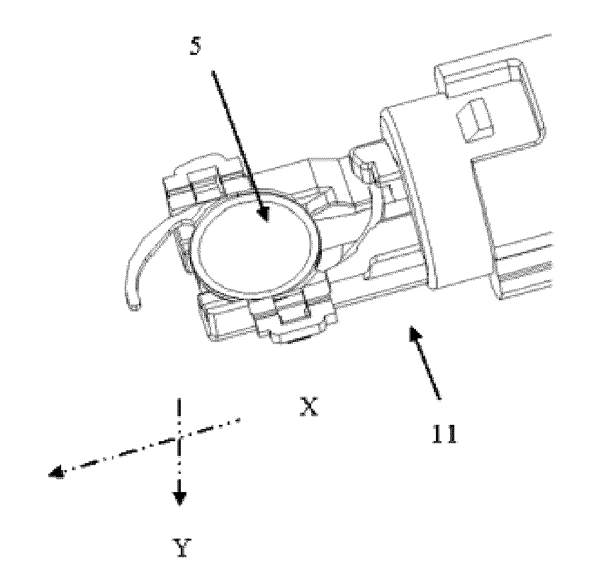
[0076] figure 1 A perspective view schematically showing the overall structure of the preassembled intraocular lens implanter 1 of the present invention. Such as figure 1 As shown in , the preassembled intraocular lens implanter 1 includes: a main body 3 , an implant head 2 that is plugged and fitted with the front end of the main body 3 , and a spiral tube 4 connected with the rear end of the main body 3 . The intraocular lens 5 is pre-placed inside the main body 3, and the intraocular lens 5 has an optical part 6 and a pair of haptics (including anterior haptic 7a and posterior haptic 7b, such as figure 2 shown).

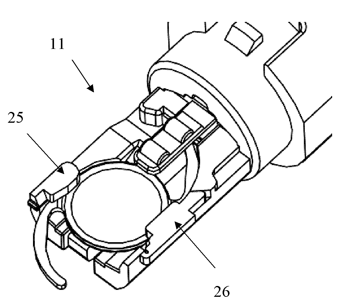
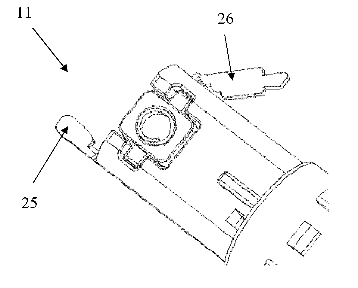
[0077] figure 2The constituent parts of the pre-assembled intraocular lens implanter 1 are clearly shown through an exploded view. The main body 3 includes an intraocular lens bearing part 11 at its front end and a main body rear end 12 connected with the spiral tube 4 . The intraocular lens 5 is pre-placed on the intraocular lens bearing part 11 at the fro...

no. 2 approach

[0084] The carrying elastic piece 16 can also be a separate component. Figure 14a and Figure 14b It is an assembly perspective view schematically showing that the carrying elastic piece 16 and the IOL carrying part 11 at the front end of the main body are two separate parts connected together by snap-fitting. It can be seen from the figure that the limiting pressing piece 21, as a separate component, is connected with the IOL bearing part 11 at the front end of the main body through the buckle at the rear end. Figure 14b The sectional view shows the connection relationship between the split bearing elastic piece 21 and the artificial lens bearing part 11 at the front end of the main body.

[0085] Figure 17 is a schematic perspective view schematically showing the folding limiting sheet 15 according to the second embodiment of the present invention, wherein the intraocular lens is not loaded. Figure 17a is schematically shown Figure 17 Front projection of folded stop...

no. 3 approach

[0091] Figure 15 , Figure 16 Front and rear assembled views of an axial bearing block according to a third embodiment of the invention are shown.

[0092] From Figure 16 It can be seen more clearly that the assembly parts of the axial bearing block are composed of a split bearing block 22 and a spring 23, and the spring 23 is assembled in the hole of the split bearing block 22, so that the axial bearing block 22 can be mounted on the spring. Under the action, it moves along the Y-axis direction, and the guide protrusion 22a on the axial bearing block 22 is assembled in the bearing block guide groove 24 on the back of the IOL bearing part at the front end of the main body, so that the position of the axial bearing block 22 in the X-axis direction is constrained fixed. The structure here can also realize the function of carrying the elastic piece 16 as described in the aforementioned first and second embodiments.

[0093] 4. Fourth Embodiment

[0094] Figure 23a and ...


PUM


Abstract

The invention relates to a preset intraocular lens implanter, comprising a main body including an intraocular lens bearing part at the front end and an intraocular lens preset on the intraocular lens bearing part, an implanting head connected with the front end of the main body and an injection driving mechanism connected with the rear end of the main body. The preset intraocular lens implanter is characterized in that the intraocular lens bearing part is provided with a pop-up structure for preventing the preset intraocular lens from moving to the implanting head before injection and a limiting component capable of restraining the preset intraocular lens to move in the vertical direction of the axial direction of the preset intraocular lens implanter. According to the preset intraocular lens implanter, the implantation of the intraocular lens can be finished only by a single operational step and the intraocular lens is simply restrained in the preset intraocular lens implanter and has rational performance.

Description

technical field [0001] The present invention relates to an artificial lens implanter. More specifically, the present invention relates to a novel pre-installed intraocular lens implanter with simple operation and reliable performance. Background technique [0002] An intraocular lens is a type of artificial lens, and in cataract surgery, the technique of implanting an intraocular lens to replace the natural intraocular lens in a person's eye clouded by cataract disease has been widely practiced. The shape of an intraocular lens usually consists of a central circular optic and peripheral haptics. Due to the different materials for processing intraocular lenses, intraocular lenses are divided into hard intraocular lenses whose optics are made of hard materials such as PMMA, and soft IOLs whose optics are made of flexible materials such as silicon elastomers, hydrogels, and soft acrylates. crystals. IOLs made of soft materials are also often called collapsible IOLs. [0003...

Claims


Application Information

Patent Timeline
Patent Type & Authority Applications(China)
IPC IPC(8): A61F2/16A61F9/007
Inventor 赵力军
Owner EYEBRIGHT MEDICAL TECH BEIJING
Why Eureka
Try Eureka