Aircraft pressure detection equipment and application method thereof

A technology for detecting equipment and pressure, applied in the direction of measuring fluid pressure, measuring devices, instruments, etc., can solve the problems of large pressure error, easy aging and error of high-pressure resistant rubber tubes, etc., to reduce measurement errors and pressure loss, good resistance Pressure resistance to high and low temperature performance, ensuring the effect of bonding and sealing performance

Pending Publication Date: 2018-02-27
闫晓红
View PDF2 Cites 4 Cited by
  • Summary
  • Abstract
  • Description
  • Claims
  • Application Information

AI Technical Summary

Problems solved by technology

The net weight of the inspection instrument is 2.0 kg, and the product interface is easily damaged during use
[0004] 2. The volume is large. The total weight of the inspection instrument together with the protective box is generally more than 4.5 kg. The size of the box is generally 40 cm x 30 cm x 15 cm. It is inconvenient to carry and use for daily use, and the air co-rotation takes up the capacity
The above separation design leads to an increase in the volume and weight of the detector, and the pressure loss of the product cavity before and after measurement is large, resulting in errors
High-pressure resistant rubber tubes are prone to aging during use, and the aging degree needs to be checked regularly to ensure the pressure resistance requirements. If the detection is not in place, the measurement accuracy

Method used


Image

  • Aircraft pressure detection equipment and application method thereof
  • Aircraft pressure detection equipment and application method thereof

Examples


Embodiment Construction

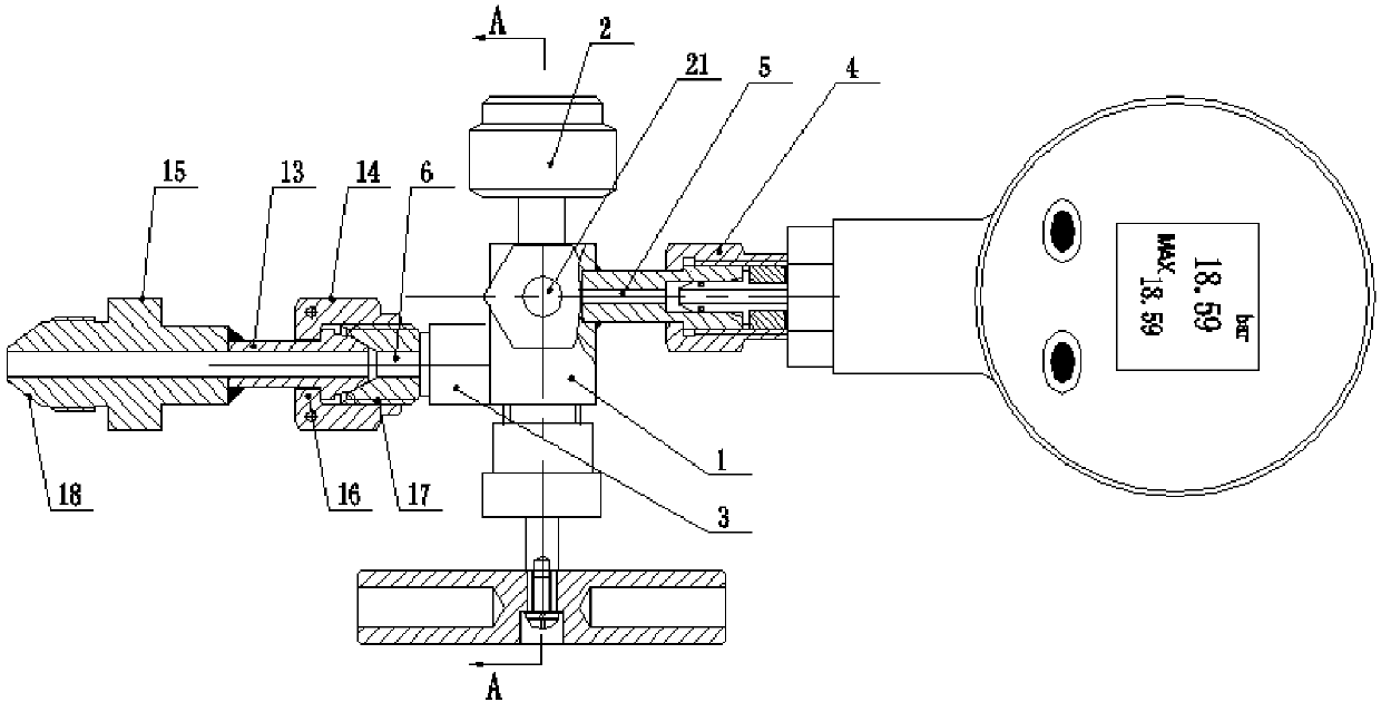
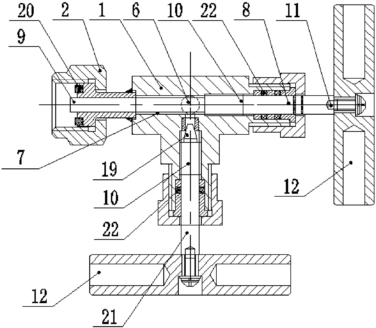
[0049] An aircraft pressure detection device, characterized in that it includes a valve body 1, a product interface 2, an inflation and deflation interface 3, and a measurement interface 4, and the valve body 1 is provided with a measurement channel 5, an inflation and deflation channel 6, and a product connection channel 7. The inflation and deflation passage 6 and the product connection passage 7 are connected to the measurement passage 5 respectively, the inflation and deflation passage 6 is provided with a stop valve 21 , and the product connection passage 7 is provided with a sealing ejector rod 8 .

[0050]Also includes an adapter 13, the adapter 13 includes a connecting pipe head 14 and an air source connecting head 15, the connecting pipe head 14 is provided with a sealing chuck 16 and an adapter thread 17, and the air source connecting head 15 is provided with a sealing surface 18. The adapter thread 17 is connected to the inflation and deflation interface 3, and the c...


PUM

PropertyMeasurementUnit
Pressure valueaaaaaaaaaa

Abstract

The invention relates to the technical field of pressure detection, in particular to aircraft pressure detection equipment and an application method thereof. The aircraft pressure detection equipmentis especially suitable for the implementation of nitrogen gas inflation, deflation and pressure measurement operation on an aircraft main landing gear buffering pillar, a front landing gear bufferingpillar and a hydraulic pressure accumulator or an emergency landing gear pneumatic system. The aircraft pressure detection equipment comprises a valve body, a product connection port, a gas inflationand deflation connection port and a measuring connection port, and the valve body is internally provided with a measuring channel, a gas inflation and deflation channel and a product connection channel and internally connected with the three channels, so that not only is the ventilation connection strength improved, but also the space of a connection cavity, the measurement errors and the pressureloss are reduced. The gas inflation and deflation channel and the product connection channel are communicated with the measuring channel separately, the gas inflation and deflation channel is provided with a sealing stop valve used for accurately controlling the opening degree of the gas inflation and deflation channel, the product connection channel is provided with a sealing top rod, and a one-way valve of a product is controlled by rotating the sealing top rod to open or close the air path of the product.

Description

technical field [0001] The invention relates to the technical field of pressure detection, in particular to an aircraft pressure detection device and a method for using the same. It is especially suitable for nitrogen inflation, deflation and pressure measurement operations on the main landing gear shock strut, front landing gear shock strut, hydraulic pressure accumulator or emergency landing gear pneumatic system. Background technique [0002] Aircraft maintenance work often uses the pillar pressure checker, which is mainly used for the measurement and inflation / deflation of nitrogen pressure in the main landing gear buffer pillar, front landing gear buffer pillar, hydraulic accumulator and emergency landing gear pneumatic system. . The main problems of existing equipment are as follows: [0003] 1. Heavy weight. The net weight of the inspection instrument is 2.0 kg, and the product interface is easily damaged during use. [0004] 2. The volume is large. The total weig...

Claims


Application Information

Patent Timeline
IPC IPC(8): G01L11/00G01L19/00
CPCG01L11/00G01L19/00G01L19/0007
Inventor 闫晓红钟伟锋
Owner 闫晓红
Why Eureka
Try Eureka