Apparatus and method for adjustment of transmitter power in a wireless system

A technology for transmitting power levels and transmitters, applied in power management, transmission systems, wireless communications, etc.

Active Publication Date: 2013-04-03
QUALCOMM INC
View PDF6 Cites 6 Cited by
  • Summary
  • Abstract
  • Description
  • Claims
  • Application Information

AI Technical Summary

Problems solved by technology

Likewise, users may depend on mu

Method used


Image

  • Apparatus and method for adjustment of transmitter power in a wireless system
  • Apparatus and method for adjustment of transmitter power in a wireless system
  • Apparatus and method for adjustment of transmitter power in a wireless system

Examples


Embodiment Construction

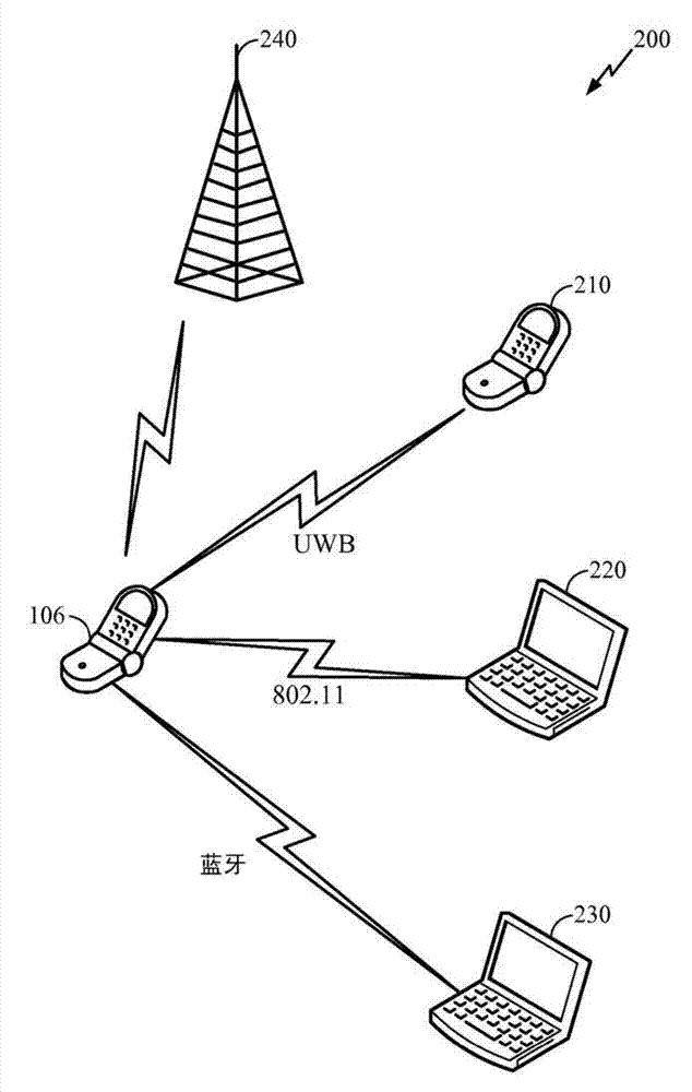
[0028] Wireless communication devices (eg, mobile cellular telephones, personal data assistants, laptop computers, etc.) are often subject to regulatory radio frequency (RF) safety requirements. Before these systems can reach the market, they must operate under specific guidelines. For example, equipment operating near the human body is evaluated to determine its specific absorption rate (SAR) of electromagnetic wave production. SAR is the time rate of absorption of electromagnetic energy per mass unit in a lossy medium, which can be expressed as follows:

[0029] SAR ( r ) = σ ( r ) ρ ( r ) | E ( r ) ...


PUM


Abstract

Certain aspects of the present disclosure propose methods for determining power level of one or more transmitters based on a power level of a primary transmitter (302) when the transmitters are located in close proximity of each other. The power levels may be determined such that a combined power of all the transmitters is compliant with regulatory radio frequency (RF) safety requirements. For certain aspects, power level of the lower priority transmitters (306) may be determined utilizing one or more look-up tables. For another aspect, power level of the lower priority transmitters may be calculated using an algorithm based on the power level of the priority transmitter. In aspects, the power level of lower priority transmitters and the time duration for which the transmitters are active may be selected dynamically so that the time averaged power of the transmitters for a defined period of time falls below the RF exposure limit.

Description

[0001] Claiming Priority Based on 35 U.S.C. §119 [0002] This patent application claims U.S. Provisional Application No. 61 / 367,767, filed July 26, 2010, entitled "Apparatus and Method for Adjustment of Transmitter Power of a Multi-Transmitter Communications Device," and filed March 1, 2011 Priority to U.S. Provisional Application No. 61 / 448,110, filed "Apparatus and Method for Adjustment of Transmitter Power of a Multi-Transmitter Communications Device," both of which have been assigned to the assignee of the present application, It is hereby expressly incorporated herein by reference. technical field [0003] In general, certain aspects of the invention relate to transmitting devices, and more particularly, to methods and systems for devices that include one or more transmitters. Background technique [0004] Wireless communication systems have been widely deployed to provide various types of communication, such as voice, packet data, and so on. These systems may be mul...

Claims


Application Information

Patent Timeline
IPC IPC(8): H04W52/34H04W52/28H04B1/38H04W52/22H04W52/42H04W52/30
CPCH04B1/3838H04W52/30Y02B60/50H04W52/42H04W52/226H04W52/281H04W52/22H04W52/28H04W52/34
Inventor J·A·福里斯特P·古基安L·卢R·沙希迪A·马哈詹W·M·哈姆迪F·M·恩盖
Owner QUALCOMM INC
Why Eureka
Try Eureka