Screw compressor

A screw compressor and screw technology, applied in mechanical equipment, machines/engines, liquid fuel engines, etc., can solve the problems of the change of the resonant frequency of the rotor shaft system and the inability to obtain vibration attenuation, and achieve the effect of reducing vibration

Active Publication Date: 2013-04-10
코벨코컴프레서가부시키가이샤
View PDF8 Cites 4 Cited by
  • Summary
  • Abstract
  • Description
  • Claims
  • Application Information

AI Technical Summary

Problems solved by technology

[0005] However, in the method based on a vibration damping device such as a dynamic vibration absorber, there is a problem that when the installation conditions of the anti-vibration rubber part, etc. are changed due to deterioration of the rubber, looseness of the mounting, etc., the resonance frequency of the rotor shaft system part changes, but the vibration damping effect cannot be obtained
[0013] In addition

Method used


Image

  • Screw compressor
  • Screw compressor
  • Screw compressor

Examples


no. 1 approach

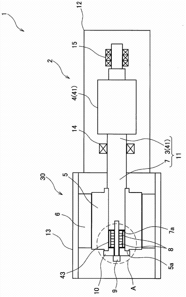
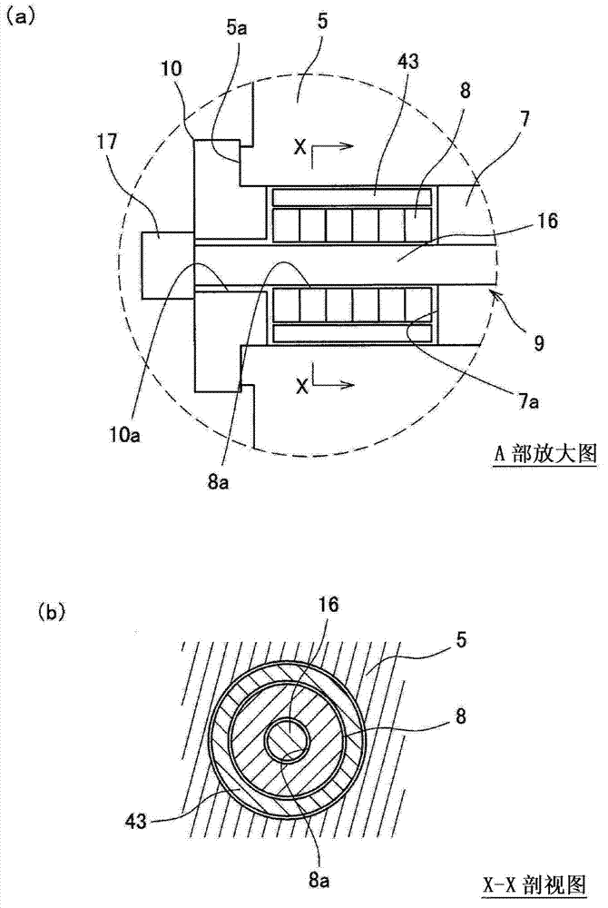
[0043] figure 1 It is a schematic side sectional view showing the screw compressor 1 according to the first embodiment of the present invention. figure 2 Yes figure 1 An enlarged view of part A ( figure 2 (a)) and its X-X sectional view ( figure 2 (b)).

[0044] (Composition of screw compressor)

[0045] Such as figure 1 As shown, the screw compressor 1 is a screw compressor provided with a motor directly connected structure formed by a screw main body portion 2 and a motor portion 30 (motor).

[0046] (Screw body)

[0047] The screw body 2 has a screw rotor 41 and a screw housing 12 that houses the screw rotor 41. The screw rotor 41 has a screw tooth part 4 and a screw shaft 3 coaxial with the screw tooth part 4 and formed integrally with the screw tooth part 4. The screw shaft 3 is double-supported by the bearing 14 and the bearing 15.

[0048] The screw teeth 4 and the screw shaft 3 are manufactured by cutting or the like from a single steel material. In addition, the screw tee...

no. 2 approach

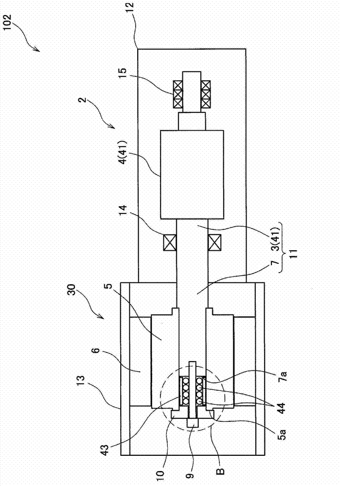
[0075] image 3 It is a schematic side sectional view showing the screw compressor 102 according to the second embodiment of the present invention. Figure 4 Yes image 3 An enlarged view of Part B ( Figure 4 (a)) and its Y-Y cross-sectional view ( Figure 4 (b)). in image 3 as well as Figure 4 Here, the same components as those of the screw compressor 1 of the first embodiment are given the same reference numerals.

[0076] The main difference between the screw compressor 1 of the first embodiment and the screw compressor 102 of this embodiment is that in the screw compressor 102 of this embodiment, a plurality of spherical bodies 44 are used as vibrating bodies.

[0077] (Sphere)

[0078] A plurality of spherical bodies 44 are inserted and arranged in a space between the cylindrical member 43 and the bolt 9 in a clearance fit manner. One spherical body 44 is arranged along the radial direction of the rotor shaft 11 on one side of the bolt 9. In this way, the plurality of spher...


PUM


Abstract

A cantilever type screw compressor directly connecting a motor has a damping structure, which is inability of generating unbalanced force during rotation of a rotor shaft and directly minimizes vibration of the rotor shaft itself. The screw compressor (1) comprises a screw rotor (41); a motor shaft (7) integrally formed with the screw rotor (41) and supported by a cantilever at the screw rotor side; and a motor which rotates the motor shaft (7). The screw compressor (1) comprises a cylinder component (43) being substantially coaxial to the motor shaft (7) and inserted between a gap between a motor side end face (7a) of the motor shaft (7) and an end component (10) in a gap fit manner along the inner surface of a rotating member (5), and a weight (8) being substantially coaxial to the motor shaft (7) and inserted in the cylinder component in a gap fit. The natural vibration frequency of the cylinder component is identical to that of the rotor shaft (11).

Description

Technical field [0001] The invention relates to a screw compressor. Background technique [0002] A screw compressor with a direct motor connection structure has higher energy conversion efficiency than a power transmission system via a drive belt. In addition, among screw compressors employing a rotational speed control method using an inverter, screw compressors with a structure where an electric motor is directly connected have become the mainstream. Here, for the purpose of cost reduction and mechanical loss reduction, a cantilever type motor-directed screw compressor is often formed without a bearing on one side of the motor shaft. [0003] The cantilever type screw compressor usually adopts the design of the rotor shaft system in such a way that the dangerous speed far exceeds the operating speed. However, in a screw compressor that generates the excitation force of the pressure pulsation component, the vibration of the rotor shaft system portion may increase when it is ope...

Claims


Application Information

Patent Timeline
IPC IPC(8): F04C18/16
CPCF04C18/16F04C29/0021F04C29/06F04C2210/22F04C2240/40F16F15/02Y10S415/00Y10S417/00
Inventor 在原广敏上田宏树本家浩一
Owner 코벨코컴프레서가부시키가이샤
Why Eureka
Try Eureka