Lancing device

a technology of laceration and laceration plate, which is applied in the field of laceration plate, can solve the problems of insufficient laceration depth, erroneous analysis, and variation of the mechanical quality of the spring, and achieves the effects of reducing protruding parts, facilitating gripping the device, and facilitating operation

Inactive Publication Date: 2004-07-01
ASCENSIA DIABETES CARE HLDG AG
View PDF13 Cites 123 Cited by
  • Summary
  • Abstract
  • Description
  • Claims
  • Application Information

AI Technical Summary

Benefits of technology

[0019] Another object is to reduce lance vibration and chatter.
[0022] Another object is to provide a compact hand-held lancing device that is easy to operate. A further object is to encase the lancing device in casings contoured to facilitate gripping the device. Another object is to provide the lancing device with external means for ensuring a consistent perpendicular lancing operation, where such means may, for example, comprise an end cap having a face perpendicular to the lancing motion.
[0023] Another object is to provide the lancing device with a flush mounted trigger or other means to reduce protruding parts that may potentially jab a user or break off. Another object is to provide a lancing device that is not prone to chattering and auto-jarring motions during the lancing operation. A further object is to provide a lancing device a reduced number of external moving pieces, such as handles, during the lancing operation.
[0024] Another object is to provide a durable, yet inexpensive, lancing device that provides consistent lance punctures over the life of one or more springs, wherein the springs may be easily replace by opening the device.

Problems solved by technology

One problem associated with other prior lancing devices is that the penetration depth of the lance is dependent on a spring constant, which is a measure of the spring stiffness.
The mechanical quality of the spring, including the stiffness, tend to vary, and in particular degrade, over time with use.
When the penetration depth of the lance lessens over time, the lance may not produce a laceration deep enough to draw the requisite volume of blood necessary for blood glucose analysis.
Insufficient lancing can result in erroneous analysis if the user does not recognize that the lancing has not produced the requisite volume of blood for analysis.
And if the user does recognize an insufficient lancing has incurred the user must re-lance resulting in another laceration in the user's skin and more pain.
The user may eventually have to replace the lance, or the entire device because the accuracy and consistency of the laceration has degraded.
Another related problem associated with many prior art lancing devices is that when the spring forwardly advances the lance to its penetration depth, the spring extends past its static length.
If the lance continues to oscillate in this manner, it may repeatedly enter the laceration and penetrate the user's skin several times. With each actuation of such an oscillating lance, the user's skin is lanced several times which results in a larger laceration.
A larger laceration in the user's skin translates into more pain for the user and a longer time for the laceration to heal.
Other problems associated with prior art lancing device include vibration and chatter of the lance during the lancing process.
The vibration and chatter result in uncontrolled movement of the lance.
Such uncontrolled movement may result in larger as well as more jagged lacerations.
Another detrimental result is inaccurate punctures in the skin, with respect to both location and depth of the puncture.

Method used


Image

  • Lancing device
  • Lancing device
  • Lancing device

Examples


Embodiment Construction

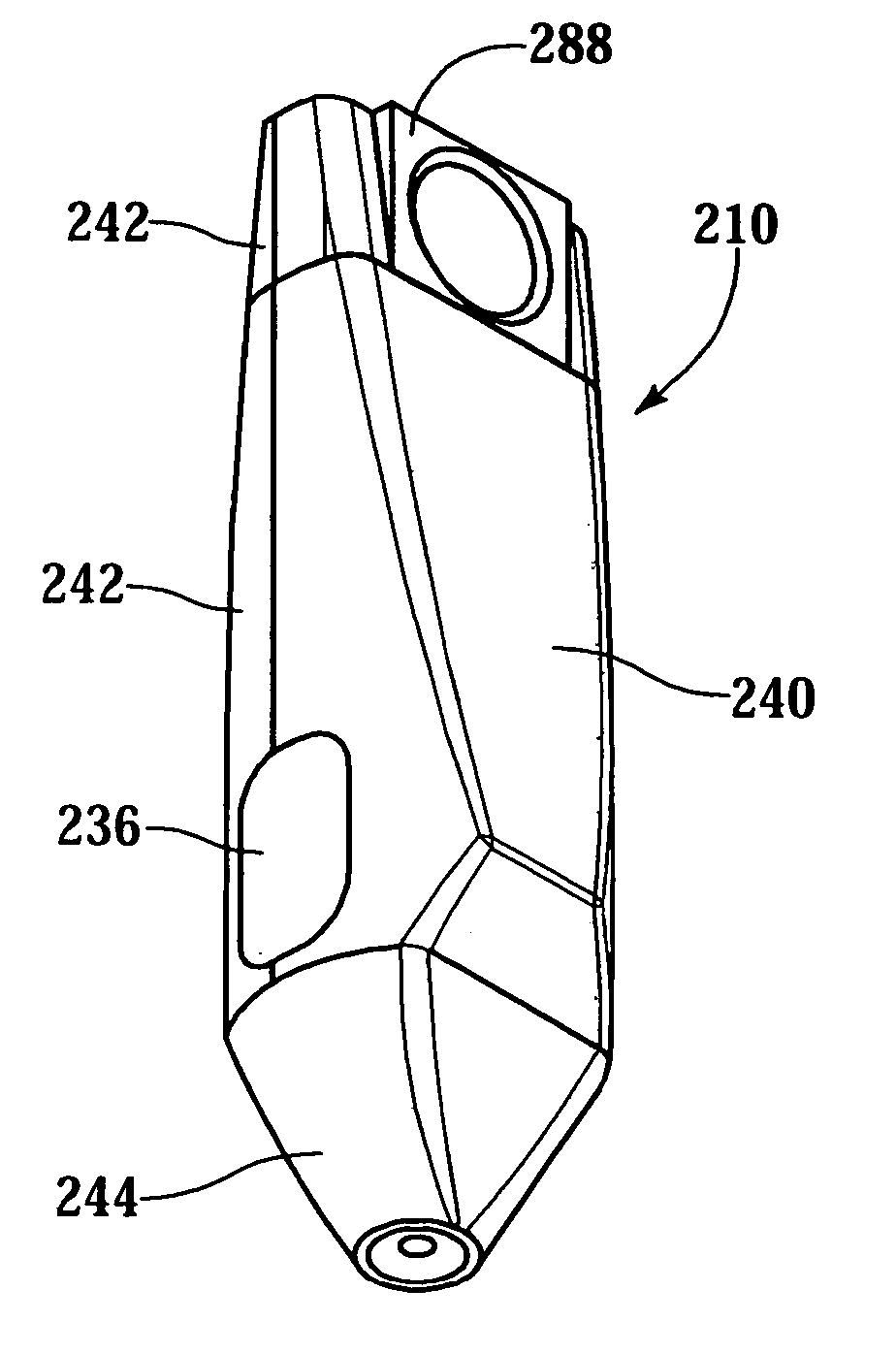
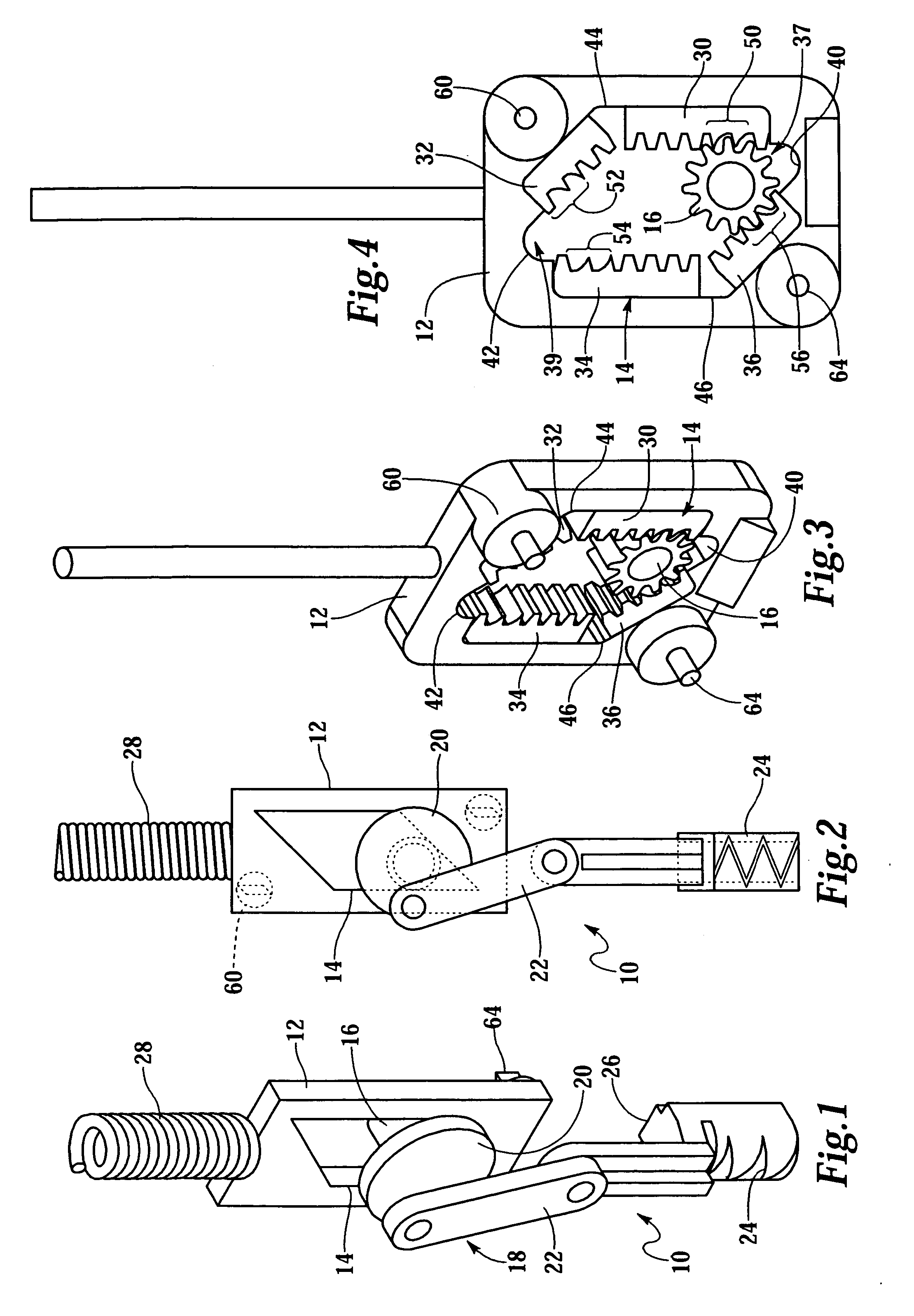
[0045] FIG. 1 shows a lancing device 10, in perspective view, for use with a lance (not shown). The device 10 comprises a frame 12 supporting a parallelogram-shaped rack 14. The rack 14 is better seen in FIG. 2 which is a side elevation view of the lancing device 10. FIGS. 3 and 4 show the reverse side of the frame 12 shown in FIGS. 1 and 2. A pinion 16 is rotatably supported in the rack 14. Rotation of the pinion 16 is coupled to movement of the rack 14. A slider-crank system 18 is coupled to the pinion 16 and comprises a drive wheel 20 and drive arm 22 coupled to a lance holder 24. The drive wheel 20 may be integral with the pinion 16. The lance holder 24 may comprise a rail 26 to interface with a slot (not shown); the lance holder 24 moves linearly in the slot in response to rotation of the pinion 16.

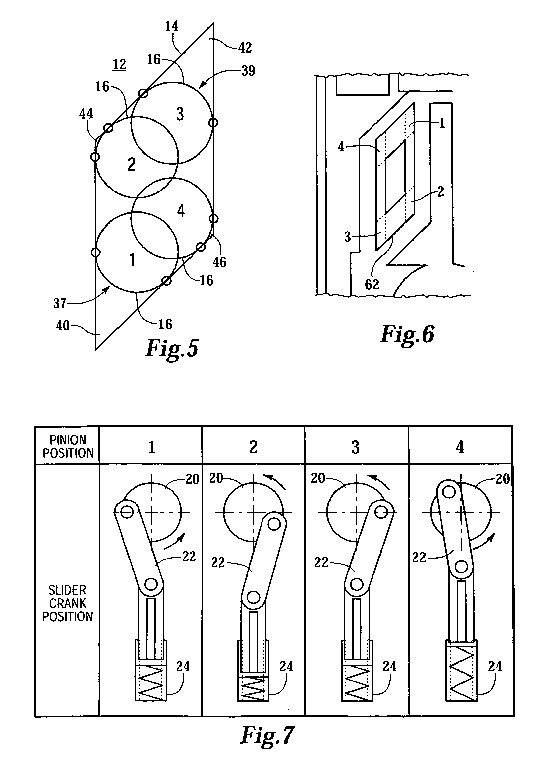
[0046] A drive spring 28 applies force to the frame 12 for moving the rack 14, wherein the pinion 16 is rotated counterclockwise (clockwise in FIGS. 3 and 4) and the slider-crank sys...


PUM


Abstract

A lancing device comprising a movable parallelogram-shaped rack. The rack rotates a linearly fixed pinion which drives a slider-crank system. The slider-crank system in turn drives a lance holder. The parallelogram-shaped rack defines one or more predetermined paths along which the pinion moves. The lance holder is prevented from being extended beyond a predetermined depth when the pinion reaches a predetermined position along the one or more predetermined paths. The pinion is mechanically stopped from further progress by intersecting two legs of the parallelogram-shaped rack. Teeth of the rack may be modified to reduce the chance the pinion may jam in the rack.

Description

[0001] The present invention relates generally to blood monitoring devices, and more particularly, to a lancing mechanism, or lancing device, for lancing a patient's skin to obtain a sample of blood for analysis.[0002] It is often necessary to quickly obtain a sample of blood and perform an analysis of the blood sample. Preferably obtaining the blood is as painless as possible. One example in which there is a need for painlessly obtaining a sample of blood is in connection with a blood glucose monitoring system where a user must frequently use the system to monitor the user's blood glucose level.[0003] One method of monitoring a person's blood glucose level is by portable handheld blood glucose testing device. The portable nature of these devices enables the user to conveniently test his blood glucose levels wherever the user may be. To check the blood glucose level, a drop of blood is obtained from him, for example, from the fingertip using a separate lancing device. The lancing de...

Claims


Application Information

Patent Timeline
Patent Type & Authority Applications(United States)
IPC IPC(8): A61B5/151A61B5/15
CPCA61B5/1411A61B5/150022A61B5/15113A61B5/15117A61B5/15128A61B5/15132A61B5/15144
Inventor WHITSON, ROBERT C.MILLER, NORMAN S.
Owner ASCENSIA DIABETES CARE HLDG AG
Why Eureka
Try Eureka