Supercharge Your Innovation With Domain-Expert AI Agents!

Lighting system

A technology for lighting devices and plate-shaped parts, applied to lighting devices, components of lighting devices, cooling/heating devices for lighting devices, etc., can solve the problems of increasing the weight of lighting devices, and achieve light weight, good heat dissipation, and lightening effect of weight

Inactive Publication Date: 2013-04-10
EYE LIGHTING SYST CORP
View PDF4 Cites 4 Cited by
  • Summary
  • Abstract
  • Description
  • Claims
  • Application Information

AI Technical Summary

Problems solved by technology

In order to meet this demand, it is necessary to provide a heat dissipation structure for the lighting device, such as heat sinks, etc., thereby increasing the weight of the lighting device

Method used


Image

  • Lighting system
  • Lighting system
  • Lighting system

Examples


Embodiment Construction

[0020] Embodiments according to the present invention will be described below with reference to the accompanying drawings.

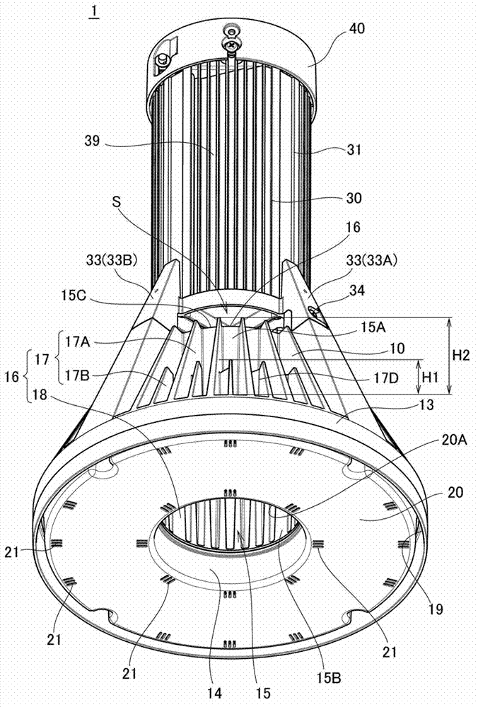
[0021] figure 1 is a diagram showing an embodiment of the lighting device 1 according to the embodiment. The lighting device 1 according to this embodiment can be suitably used as a high ceiling-mounted lighting device, and when the high ceiling-mounted lighting device is used, it is suspended from indoor ceilings of factories, gymnasiums, commercial facilities, and the like. In the present embodiment, the upper side and the lower side of the lighting device 1 represent the upper side and the lower side of the lighting device 1 when the lighting device 1 is mounted in a state suspended from the ceiling.

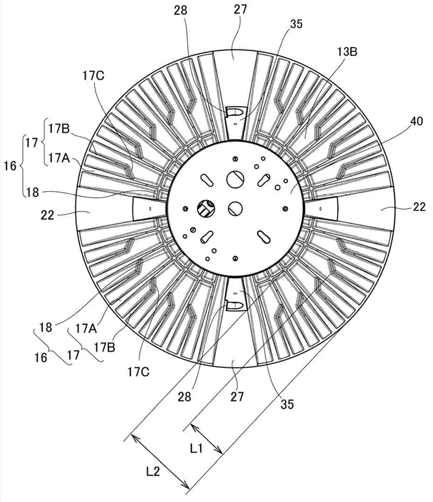
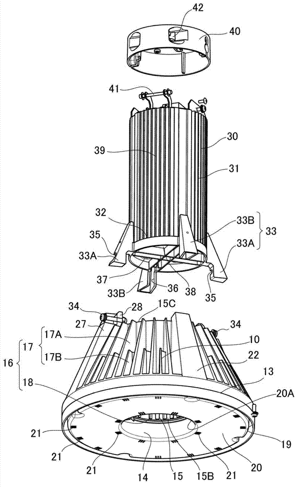
[0022] The lighting device 1 has a lamp body 10 , a box body 30 and a fixing unit 40 . The lamp body 10 is a light source unit that has a light emitting element 11 described below and applies light emitted from the light emitting element 11 through a ...


PUM


Abstract

The invention discloses a lighting system having a plate-like portion having a plurality of light emitting elements provided on the surface thereof, and a case body in which one of a power supply circuit for supplying power to the light emitting elements and a power supply wire connected to an external power supply is accommodated. The lighting system is characterized in that a through-hole is formed in the plate-like portion so as to penetrate through the plate-like portion, the light emitting elements are arranged around the through-hole, a hollow cylindrical ventilation portion having no bottom is provided to the back surface of the plate-like portion so as to intercommunicate with the through-hole, and the case body is joined to one end portion of the ventilation portion; so that a gap opened to the outside in a peripheral direction of the ventilation portion is formed between the one end portion of the ventilation portion and the case body.

Description

technical field [0001] The present invention relates to a lighting device suitable for use as a high ceiling-mounted lighting device. Background technique [0002] Indoor lighting devices installed on indoor ceilings of factories, gymnasiums, commercial facilities, etc. are called high ceiling-mounted lighting devices (for example, see JP-A-2009-301718). [0003] In order to achieve energy saving and increase in lifespan of a high ceiling-mounted lighting device, it has been considered to use a light emitting element such as a light emitting diode (LED) as a light source of the lighting device. However, when a light emitting element such as an LED is used as a light source, it is necessary to efficiently dissipate heat generated from the light emitting element and a mounting board on which the light emitting element is mounted. In order to meet this requirement, it is necessary to provide a heat dissipation structure for the lighting device, such as a cooling fin, which inc...

Claims


Application Information

Patent Timeline
IPC IPC(8): F21S2/00F21V29/00F21V23/00
CPCF21V17/12F21V29/75F21Y2115/10
Inventor 三浦正义木下庆一郎
Owner EYE LIGHTING SYST CORP
Features
  • R&D
  • Intellectual Property
  • Life Sciences
  • Materials
  • Tech Scout
  • Unparalleled Data Quality
  • Higher Quality Content
  • 60% Fewer Hallucinations
Learn More