Switch

A technology of switches and concave parts, which is applied in the direction of electric switches, emergency actuators, electrical components, etc., can solve the problems of inability to recover elastically, plastic deformation of movable electrodes, and damage of pressing parts, so as to achieve service life and avoid local stress concentration , the effect of suppressing the load

Inactive Publication Date: 2013-04-10
MITSUMI ELECTRIC CO LTD
View PDF8 Cites 8 Cited by
  • Summary
  • Abstract
  • Description
  • Claims
  • Application Information

AI Technical Summary

Problems solved by technology

As a result, the movable electrode deforms plastically and becomes irrecoverable elastically
In addition, since the presser part with high rigidity cannot be deformed with the elastic deformation of the movable electrode, local concentration of stress will occur, which will not only cause plastic deformation of the movable electrode, but also cause damage and sticking of the presser part. pick-up problem
[0008] In addition, if the switch is subjected to an unexpected shock, the pusher part with high rigidity will hit the movable electrode, resulting in plastic deformation of the movable electrode and breakage of the pusher part
As a result, the function required by the switch cannot be maintained

Method used


Image

  • Switch
  • Switch
  • Switch

Examples


Embodiment Construction

[0030] Embodiments of the present invention will be described in detail below with reference to the drawings. In addition, in each of the drawings used in the following description, in order to clearly show each component, appropriate scale adjustments have been made.

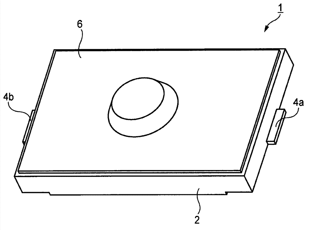
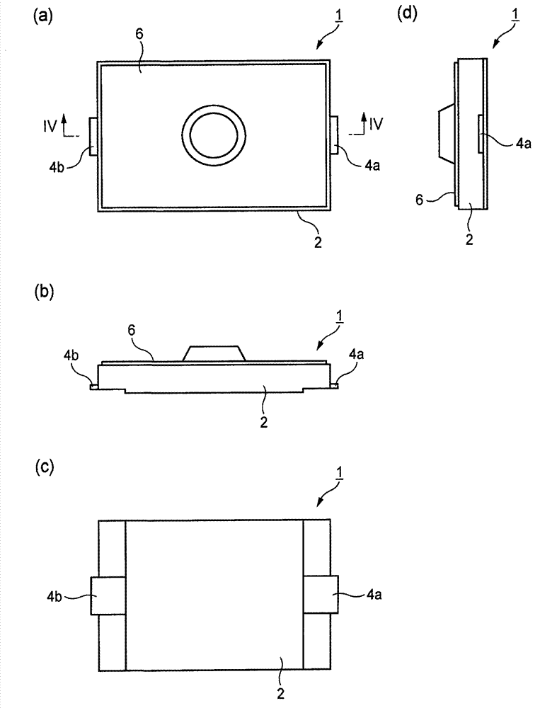
[0031] As an embodiment of the switch related to the present invention, figure 1 shows a perspective view of the push switch 1, figure 2 Represents a four-sided graph. exist figure 2 Among them, (a) is a top view, (b) is a front view, (c) is a bottom view, and (d) is a right side view. Since the shape seen from the rear and left side is symmetrical to the shape shown in each front view and right side view, drawings are omitted.

[0032] As shown in these drawings, the push switch 1 has an appearance in which a push member 6 is provided on the upper surface of an insulating resin case 2 mounted on a circuit board.

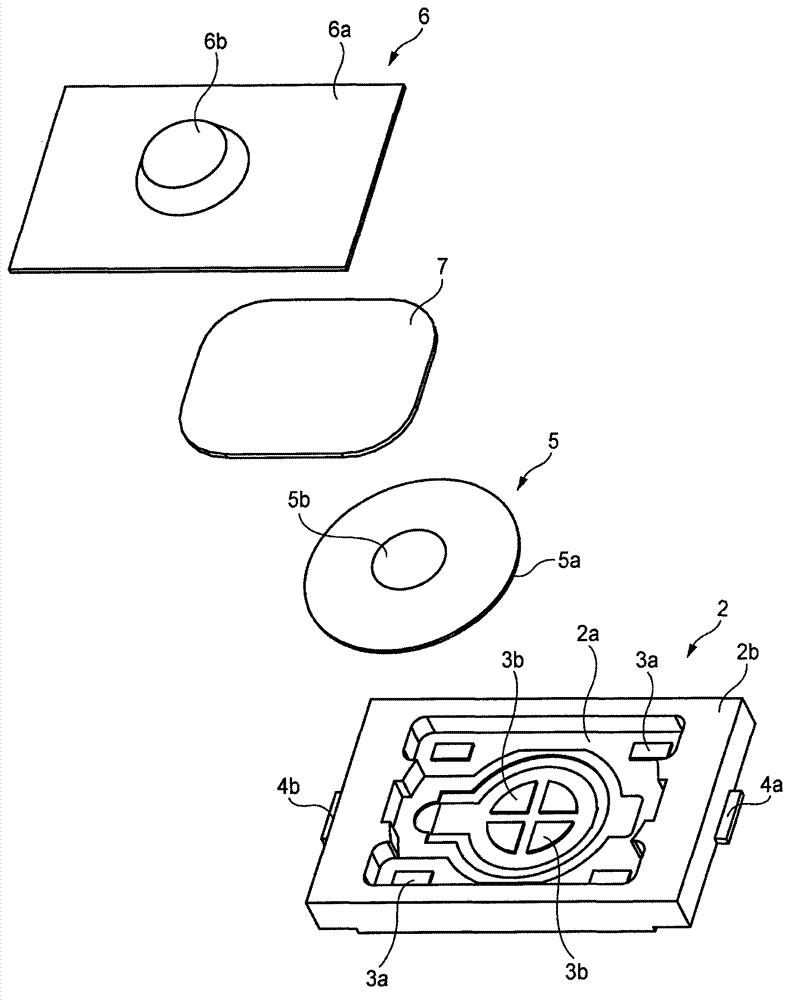
[0033] like image 3 As shown in the exploded perspective view of , the housing 2 has an ...


PUM


Abstract

A switch includes a case(2) including a recess(2a), a plurality of fixed electrodes (3a,3b)provided in the recess, a movable electrode provided in the recess, a pressing member and a buffer member. The case is mounted on a circuit board. The movable electrode is displaced between a first position where the plurality of fixed electrodes(3a,3b) are electrically connected each other and a second position where the plurality of fixed electrodes are not electrically connected each other. The pressing member(6) covers at least a portion of the recess(2a), and displaces the movable electrode from the second position to the first position by a pressing force applied from outside. The buffer member(7) is interposed between the movable electrode(5) and the pressing member(6), and is elastically deformed by the pressing force.

Description

technical field [0001] The invention relates to a switch used in various small electronic devices, in particular to a push switch installed on a circuit substrate. Background technique [0002] In this type of device, a recessed portion is formed in a case mounted on a circuit board, and a plurality of fixed electrodes and movable electrodes are arranged in the recessed portion. The movable electrode can be elastically displaced between a first position where the plurality of fixed electrodes are in a conduction state with each other and a second position where a non-conduction state is made, and the pressing member is movable in the second position normally. The electrodes are arranged in a facing manner. When the pressing member can displace the movable electrode to the first position by the pressing force from the outside, the fixed electrodes will be brought into a conduction state. When the pressing force is released, the movable electrode elastically returns to the s...

Claims


Application Information

Patent Timeline
Patent Type & Authority Applications(China)
IPC IPC(8): H01H13/48
CPCH01H13/48H01H2209/012H01H2215/012H01H2217/024H01H2221/05H01H2221/076
Inventor 菊池秀武
Owner MITSUMI ELECTRIC CO LTD
Why Eureka
Try Eureka