A pre-contact module in a capacitor contactor
A pre-contact, contactor technology, applied in relays, electromagnetic relays, electromagnetic relay details and other directions, can solve the problems of increasing the design space of contactors, difficulty in miniaturization of devices, damage to adjustment springs, etc., to avoid failure or even damage and shrinkage. Design space, the effect of enhancing reliability
- Summary
- Abstract
- Description
- Claims
- Application Information
AI Technical Summary
Problems solved by technology
Method used
Image
Examples
no. 1 approach
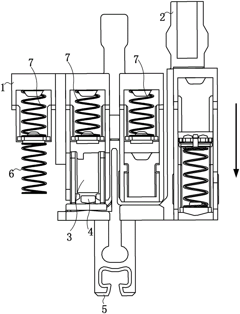
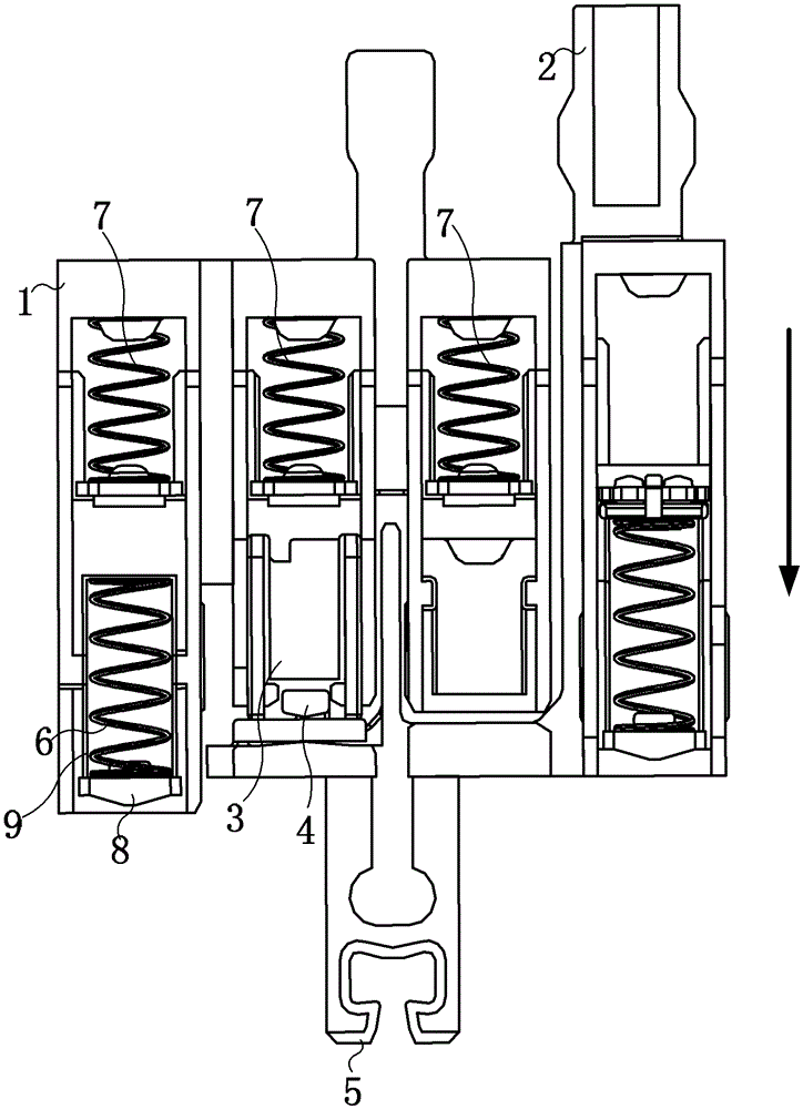
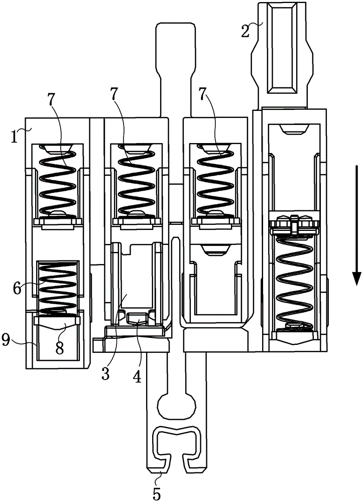
[0031] In the first embodiment of the present invention, one end of the adjustment spring close to the movable contact spring is still fixed on the pre-contact support as in the prior art, while the other end is fixed on a support plate, which can be used in a Inside the form that accommodates the adjustment spring and limits the vibration of the adjustment spring, slides in the contraction / extension direction of the adjustment spring, such as figure 2 shown. The support plate is long, such as Figure 5 As shown in , its length direction is in the figure 2 The direction perpendicular to the paper surface, so when the auxiliary support drives the pre-contact support to move in the direction indicated by the arrow, the support plate will touch the shell substrate of the capacitive contactor and stop moving, and then compress the adjustment spring in the window to Provides force to separate the two contact support parts from each other.
[0032] Next, first combine Figure ...
no. 2 approach
[0040] Figure 6 It is a front view of the pre-contact module of the capacitor contactor in the second embodiment of the present invention.
[0041] According to the second embodiment of the present invention, two adjustment springs 6 can be arranged in the pre-contact support 1, respectively arranged at positions corresponding to the two moving contact springs 7, and respectively located on both sides of the permanent magnet 3, Specific location such as Figure 6 shown. Simultaneously similar to the description in the first embodiment of the present invention, the two adjustment springs 6 each slide in a window 9 , and their two ends are respectively fixed on the pre-contact support 1 and a support plate 8 . Therefore, during the movement of the pre-contact support, the two adjustment springs are compressed together in their respective windows, which increases the force for separating the pre-contact support and the auxiliary support, and further enhances the reliability of...
Embodiment approach
[0044] According to the third embodiment of the invention, it is also possible, as in the first embodiment, to provide only one adjustment spring 6 , but it is arranged at Figure 6 The right position of the middle permanent magnet 3, rather than being set on the left side of the permanent magnet 3 as in the first embodiment. Corresponding to the adjustment spring, the design of the window, the support plate, the limit mechanism, etc. is similar to that of the first embodiment.
PUM
 Abstract
Description
Claims
Application Information
 - R&D
- Intellectual Property
- Life Sciences
- Materials
- Tech Scout
- Unparalleled Data Quality
- Higher Quality Content
- 60% Fewer Hallucinations
Browse by: Latest US Patents, China's latest patents, Technical Efficacy Thesaurus, Application Domain, Technology Topic, Popular Technical Reports.
© 2025 PatSnap. All rights reserved.Legal|Privacy policy|Modern Slavery Act Transparency Statement|Sitemap|About US| Contact US: help@patsnap.com


