Chair for director
A director's chair and chair seat technology, which is applied in the field of folding chairs, can solve the problem of single function and inconvenient table board, and achieve the effect of simple storage operation and stable table board
- Summary
- Abstract
- Description
- Claims
- Application Information
AI Technical Summary
Problems solved by technology
Method used
Image

Examples
Embodiment Construction
[0019] The present invention will be further described in detail below in conjunction with the accompanying drawings and embodiments.
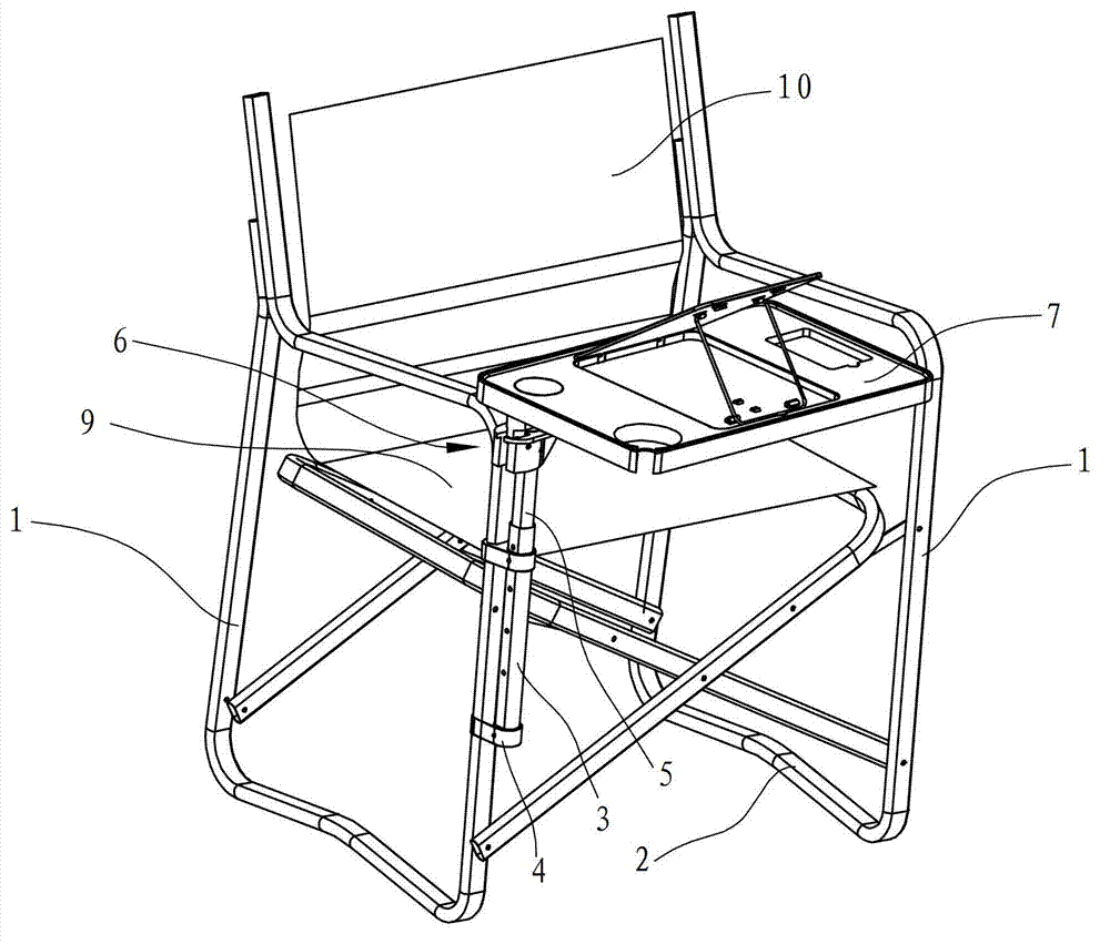
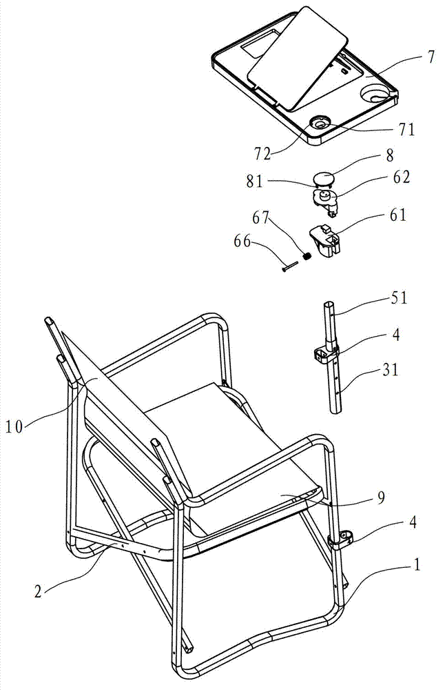
[0020] see Figure 1-Figure 3 , a director's chair, comprising seat support frames 1 on both sides, a horizontal folding support frame 2 hinged between the seat support frames 1, hinged with the seat support frame 1 so that the chair can be folded and folded, and also includes a chair Face 9 and chair back 10.
[0021] A vertical support is provided on the front side of one seat support frame 1, including a support tube 3 and a telescopic tube 5. The seat support frame 1 and the support tube 3 pass through the connecting seat 4 and are fixed respectively, so that the seat support The relative positions of the frame 1 and the support tube 3 are fixed. In this embodiment, there are two connection seats 4, which are respectively arranged on the upper and lower parts of the seat support frame 1, so that the support tube 3 can be better fixed. Th...
PUM
 Abstract
Description
Claims
Application Information