Electric die-casting machine with core-riving hydraulic unit

A hydraulic unit and die-casting machine technology, applied in the field of electric die-casting machines, can solve the problems of inability to share hydraulic units for core driving, low output grid, etc., achieve easy movement and storage, prevent the increase of installation area, easy installation and removed effect

Inactive Publication Date: 2013-07-31
TOYO MACH & METAL CO LTD
View PDF10 Cites 3 Cited by
  • Summary
  • Abstract
  • Description
  • Claims
  • Application Information

AI Technical Summary

Problems solved by technology

In addition, in the electric die-casting machine, there is also a type that uses the hydraulic pressure accumulated in the accumulator as an auxiliary power for the injection plunger. However, the hydraulic unit of this electric die-casting machine is different from that of the hydraulic die-casting machine. Compared with the existing hydraulic unit, the output is extremely low, so it cannot be shared with the core driving hydraulic unit

Method used


Image

  • Electric die-casting machine with core-riving hydraulic unit
  • Electric die-casting machine with core-riving hydraulic unit
  • Electric die-casting machine with core-riving hydraulic unit

Examples


Embodiment Construction

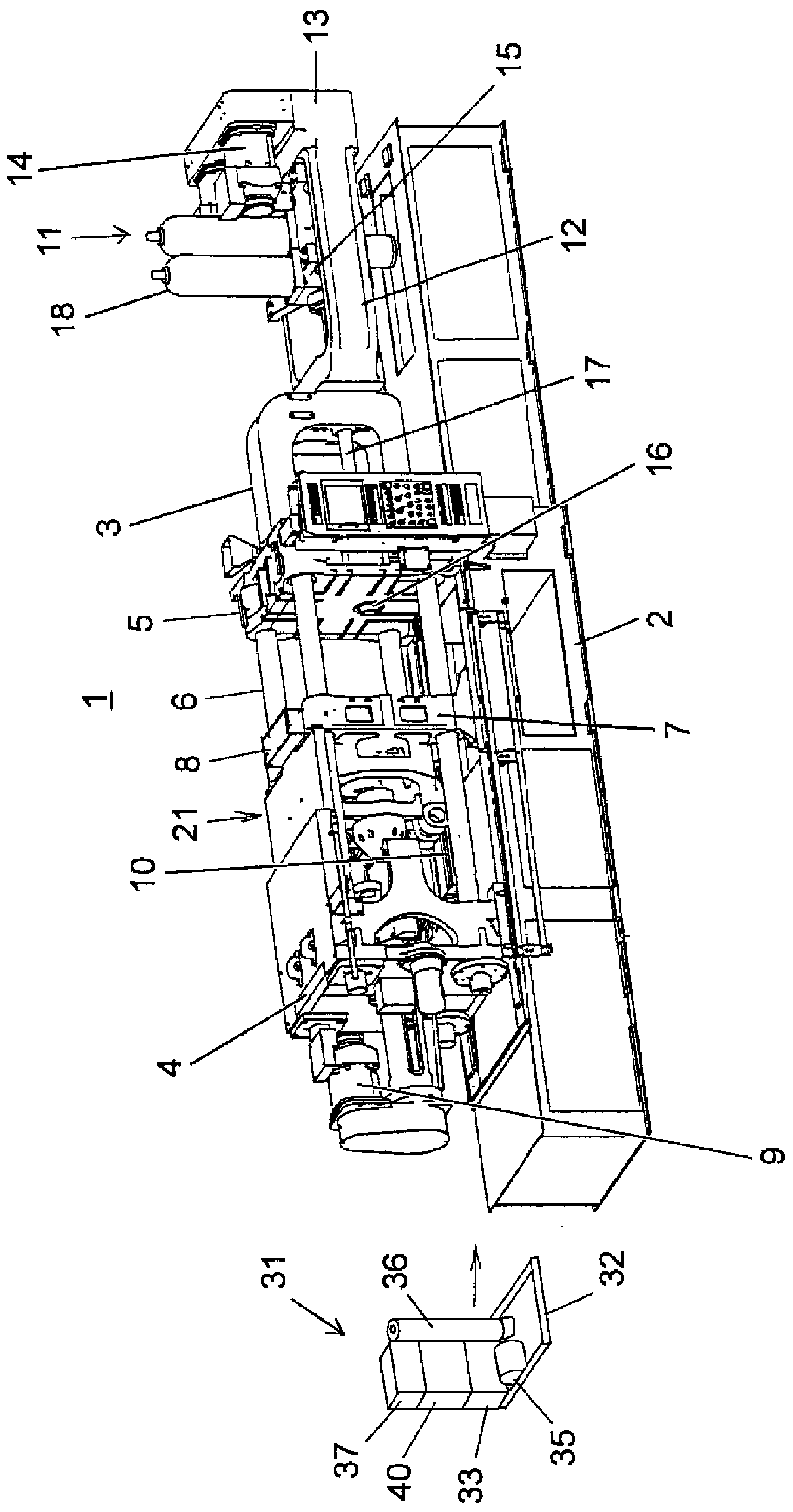
[0032] Next, an embodiment of an electric die-casting machine including a core-driving hydraulic unit according to the present invention will be described with reference to the drawings.

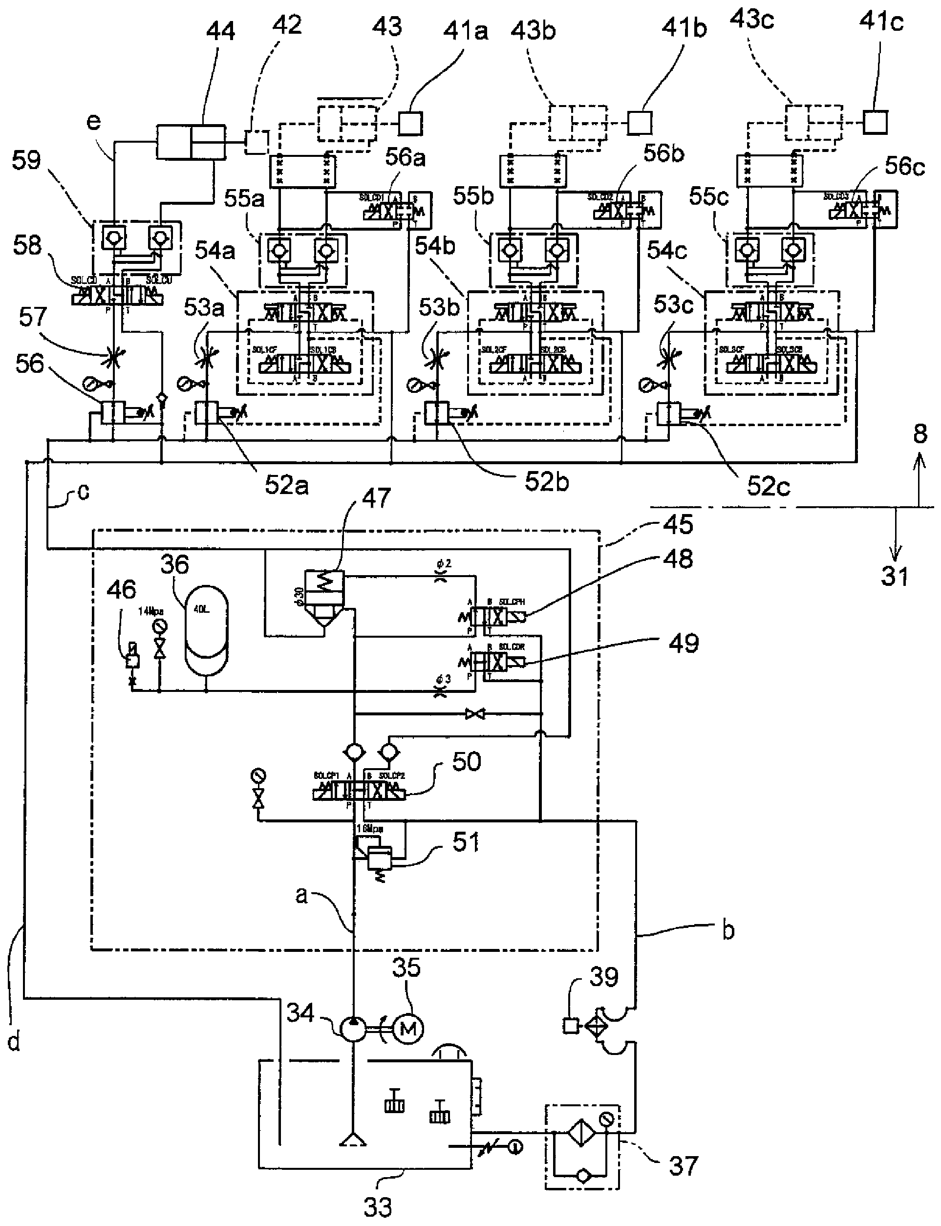
[0033] Such as figure 1 As shown, the electric die-casting machine 1 of this embodiment mainly includes a main base plate 2, a mold clamping unit 21 installed on the main base plate 2, an injection unit 11 held by the main base plate 2 and the mold clamping unit 21, and a A mold not shown on the mold clamping unit 21 and a hydraulic cylinder for driving a core of the mold (refer to figure 2 ), the core unit 8 installed on the mold clamping unit 21 , and the core driving hydraulic unit 31 detachably installed on the main base plate 2 .

[0034] A set of molds consisting of a fixed mold and a movable mold can be provided with a specified number of cores with a specified shape and size. By assembling the cores, a specified shape corresponding to the appearance shape of the product is formed i...


PUM


Abstract

[Problem] To provide an electric die-casting machine equipped with a core-driving hydraulic unit, the electric die-casting machine being configured in a manner such that, although the electric die-casting machine is equipped with the hydraulic unit, the electric die-casting machine does not require a large installation area and the maintainability of the electric die-casting machine is not compromised. [Solution] A suitable core-driving hydraulic unit (31) is configured by integrating together an oil tank (33), a hydraulic pump (34), a hydraulic pump-driving motor (35), an accumulator (36), an oil cooler (37), valves (38) including a solenoid directional control valve, an oil cleaner (39), an electric box (40), etc. in such a manner that such components are disposed on a base plate (32) doubling as an oil pan. The core-driving hydraulic unit (31) is affixed to a predetermined position on a main base board (2) in such a manner that the hydraulic pump (34) and the hydraulic pump-driving motor (35) are located below a mold-clamping electric servomotor (22) and the remaining components are located at a side of the mold-clamping electric servomotor (22).

Description

technical field [0001] The present invention relates to an electric die-casting machine provided with a hydraulic unit for driving a core, and more particularly to an arrangement and a mounting structure of the hydraulic unit for driving a core with respect to the electric die-casting machine. Background technique [0002] Die-casting machines cast products of specified shapes by injecting and filling molten metal materials (metal solution) such as aluminum alloys and magnesium alloys into the cavity formed on the mold. The speed and injection pressure are characterized by high levels. Therefore, in the past, the hydraulic die-casting machine that uses hydraulic pressure to drive the injection plunger and the drive of the mold opening and closing mechanism is the mainstream. An electric die-casting machine in which a motor drives an injection plunger and a mold opening and closing mechanism is also widespread (for example, refer to Patent Documents 1 and 2). [0003] Howev...

Claims


Application Information

Patent Timeline
Patent Type & Authority Applications(China)
IPC IPC(8): B22D17/22B22D17/26B22D17/32
CPCB22D17/26B22D17/32B22D17/229B22D17/24
Inventor 中塚吉久
Owner TOYO MACH & METAL CO LTD
Why Eureka
Try Eureka